


2-1
February 2001
Part No. 001-9800-001
INSTALLATION
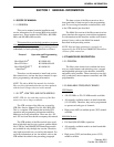
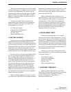
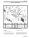
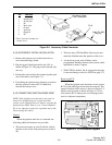
Figure 2-1 Front Mount Installation Components
Item
No.
Description Part No.
Item
No.
Description Part No.
1 Amplified dynamic microphone 250-0740-300 7 Screw, No. 10 self-drilling (4) 575-9077-545
2 Tri-knob (2) 547-0016-008 8 10-ft. DC power cable & hardware 023-9800-410
3 Standard mounting bracket 017-2229-005 9 Accessory pigtail cable (optional) 597-9800-003
4 Microphone hanger 023-3514-001 10 Accessory wire kit (optional) 023-9750-011
5 Screw, 4-24 x 5/16” sheet metal (3) 575-3604-010 11 5”, 4.7 ohm external spkr (optional) 250-0151-010
6 Hanger grounding wire assembly 023-7171-911
Miniature UHF
Jack
1
2
2
3
4
5
6
7
8
11
10
Antenna
10 ft
Install
15A Fuse
Optional
Speaker
Optional
9
6 ft
2.1 GENERAL
2.1.1 SCOPE OF INSTRUCTIONS
Since each installation is somewhat unique, the
installation instructions which follow are intended
only as a general guide to installing this transceiver.
2.1.2 PERFORMANCE TESTS
Although each transceiver is carefully tested and
aligned at the factory, it is good practice to verify
transceiver performance before it is placed in service.
Performance tests are located in Sections 7.5 and 7.6.
SECTION 2 INSTALLATION