


A part’s listing in this catalog does not guarantee its availability.
To download/print the most current catalog, go to www.lordfulfi llment.com/upload/PC7000.pdf. Rev.1 10/08
Page 92 of 124
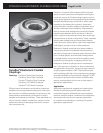
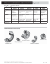
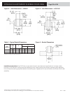
DYNAFLEX ELASTOMERIC FLEXIBLE COUPLINGS
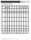
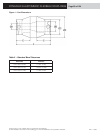
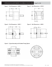
Notes: Maximum recommended misalignment - 1/32 inch parallel, 2° angular.
Intrusion should not exceed “E” bore length dimensions.
Coupling Part
Number
Standard Bore
Diameters
C
(in)
D Ref.
(in)
E Ref.
(in)
F
(in)
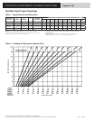
HP at
1750 rpm
Ref.
Torque
Rating
(lb-in)
Static
Torsional
Stiffness
(lb-in/deg)
±20%
Set
Screw
Size
A (in) B (in)
SK-1947-6 0.125 0.125
0.44 0.56 0.36 0.81 1/50 0.8 0.053 5/40
SK-1947 0.187 0.187
SK-1947-19 0.187 0.250
SK-1947-29 0.250 0.250
J-1211-1-2 0.187 0.187
0.63 0.81 0.56 1.38 1/16 2.50 0.17 10/24
J-1211-1-1 0.250 0.250
J-1211-2-2 0.250 0.250
0.75 1.00 0.72 1.75 1/8 5 0.33 10/24
J-1211-2-11 0.250 0.312
J-1211-2-6 0.250 0.375
J-1211-2-3 0.312 0.312
J-1211-2-12 0.312 0.375
J-1211-2-1 0.375 0.375
J-1211-3-4 0.312 0.312
0.88 1.25 0.88 2.13 1/4 10 0.66 1/4-20
J-1211-3-14 0.312 0.375
J-1211-3-12 0.312 0.500
J-1211-3-2 0.375 0.375
J-1211-3-8 0.375 0.500
J-1211-3-1 0.500 0.500
J-1211-4-2 0.375 0.375
1.00 1.38 0.91 2.25 1/3 13 0.87 1/4-20
J-1211-4-35 0.375 0.500
J-1211-4-11 0.375 0.625
J 1211-4-14 0.500 0.500
J-1211-4-4 0.500 0.625
J-1211-4-1 0.625 0.625
J-1211-5-3 0.500 0.500
1.13 1.63 1.00 2.50 1/2 20 1.33 1/4-20
J-1211-5-4 0.500 0.750
J-1211-5-2 0.625 0.625
J-1211-5-1 0.750 0.750
J-1211-6-12 0.500 0.500
1.38 1.81 1.05 2.69 3/4 30 2.00 5/16-18 J-1211-6-18 0.625 0.625
J-1211-6-14 0.625 0.750
J-1211-7-16 0.500 0.750
1.50 2.00 1.11 2.88 1 40 2.66 5/16-18 J-1211-7-9 0.625 0.625
J-1211-7-3 1.00 1.00
Standard Construction: Hubs - steel; Bores - as listed; Set Screws - one per hub furnished but
not installed; Flexing Element - neoprene.
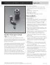
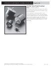
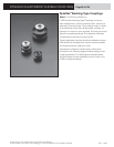
Dynafl ex Shear-Type Couplings
Table 1 – Specifi cations and Dimensions