


A part’s listing in this catalog does not guarantee its availability.
To download/print the most current catalog, go to www.lordfulfi llment.com/upload/PC7000.pdf. Rev.1 10/08
Page 114 of 124
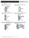
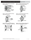
DYNAFLEX ELASTOMERIC FLEXIBLE COUPLINGS
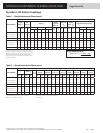
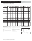
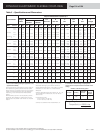
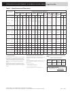
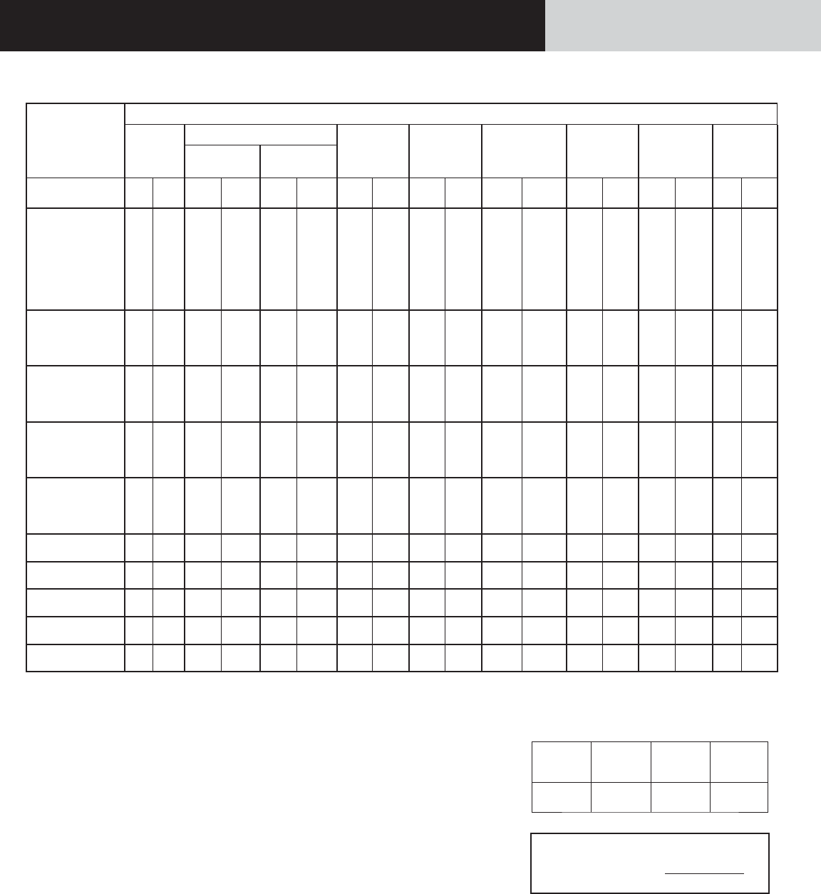
Table 3 – Specifi cations and Dimensions
Part Number*
Physical Characteristics (Nominal)
Weight
Mass
Inertia
A
Pilot O.D.
B
B.C. Dia.
C
Dia.
D
Dia.
E
Dia.
F
Length
Inner
Member
Outer
Member
Size
Variation lb kg
lb-in-
sec
2
kg-m
2
lb-in-
sec
2
kg-m
2
in mm in mm in mm in mm in mm in mm
LCD-0075
-XR-A
-XXR-A
6.5
8.3
2.95
3.76
0.04 0.004
0.21
0.35
0.024
0.039
8.500
12.375
215.90
314.33
7.875
11.625
200.03
295.28
2.875
73.03
3.375 85.73
No
Counter
Bore
No
Counter
Bore
2.62 66.55
LCD-0075
-XR-C
-XXR-C
6.5
8.3
2.95
3.87
0.04 0.004
0.21
0.35
0.024
0.039
8.500
12.375
215.90
314.33
7.875
11.625
200.03
295.28
2.875
73.03
3.375 85.73
No
Counter
Bore
No
Counter
Bore
2.62 66.55
LCD-0075
-X-C 6.3 2.87 0.04 0.004 0.07 0.007 10.340 262.58 9.625 244.48 2.813 71.45 3.313 84.14 2.688 68.28 2.00 50.8
LCD-0150 -XR-A
-XXR-A
20
13.8
9.07
6.26
0.13
0.08
0.015
0.009
0.29 0.033 12.375 314.33 11.625 295.28
2.875
2.500
73.03
63.50
3.375
3.400
85.73
86.36
4.25
4.57
107.95
120.65
2.80 71.12
LCD-0150 -XR-C
-XXR-C
20
13.8
9.07
6.26
0.13
0.08
0.015
0.009
0.29 0.033 12.375 314.33 11.625 295.28
2.875
2.500
73.03
63.50
3.375
3.400
85.73
86.36
4.25
4.57
107.95
120.65
2.80 71.12
LCD-0200 -XR-A
-XXR-A
21
16
9.52
7.26
0.22
0.09
0.025
0.010
0.69 0.078 13.875 352.42 13.125 333.38
4.000
2.500
101.60
63.50
4.625
3.400
117.47
86.36
5.50
5.33
139.70
135.38
2.80 71.12
LCD-0200 -XR-C
-XXR-C
21
16
9.52
7.26
0.22
0.09
0.025
0.010
0.69 0.078 13.875 352.42 13.125 333.38
4.000
2.500
101.60
63.50
4.625
3.400
117.47
86.36
5.50
5.33
139.70
135.38
2.80 71.12
LCD-0300 -XR-A
-XXR-A
33
18
14.96
8.16
0.59
0.25
0.067
0.028
0.92 0.104 13.875 352.42 13.125 333.38
4.000
4.000
101.60
101.60
4.625
5.125
117.47
130.18
6.00
6.69
152.40
170.00
3.06 77.72
LCD-0300 -XR-C
-XXR-C
33
18
14.96
8.16
0.59
0.25
0.067
0.028
0.92 0.104 13.875 352.42 13.125 333.38
4.000
4.000
101.60
101.60
4.625
5.125
117.47
130.18
6.00
6.69
152.40
170.00
3.06 77.72
LCD-0400 -X-A
-XX-A
45
48
20.41
21.77
0.57
0.93
0.065
0.150
2.83 0.320 13.875 352.42 13.125 333.38
6.000
4.000
152.40
101.60
7.000
4.625
177.80
117.47
8.00
6.00
203.20
152.4
2.75 69.85
LCD-0400 -X-C
-XX-C
45
48
20.41
21.77
0.57
0.93
0.065
0.150
2.83 0.320 13.875 352.42 13.125 333.38
6.000
4.000
152.40
101.60
7.000
4.625
177.80
117.47
8.00
6.00
203.20
152.4
2.75 69.85
LCD-0600 -X-A
-X-C
62 28.11 1.12 0.127 5.23 0.591 15.500 393.70 14.625 371.47
6.000
152.40
7.000 177.80 8.00 203.20 3.00 76.20
LCD-0800 -X-A
-X-C
81 36.60 1.25 0.141 8.21 0.928 17.000 431.80 16.250 412.75 7.500 190.50 8.500 215.90 9.50 241.30 3.50 88.90
LCD-1000 -X-A
-X-C
105 47.62 3.51 0.397 14.57 1.647 19.000 482.60 18.125 460.37 8.825 224.16 10.125 257.18 11.52 292.61 4.00 101.60
LCD-1500 -X-A
-X-C
160 72.58 6.23 0.704 32.50 3.673 22.500 622.22 21.375 542.93 10.000 254.00 11.500 292.10 13.25 336.55 4.25 107.95
LCD-2000 -X-A
-X-C
160 72.58 7.40 0.836 31.48 3.557 22.500 622.22 21.375 542.93 11.500 292.19 13.250 336.55 15.25 387.35 4.25 107.95
* Please consult LORD engineering for application review,
approval and availability.
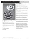
Prolonged exposure to temperatures in the 0°F range and
below produces a signifi cantly reduced slip torque prior to
driveline warm-up. This condition may result in the coupling’s
inability to transmit adequate drive torque for applications
experiencing unusual cold temperature related parasitic
loading.
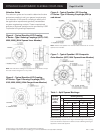
Blind assembly style with a notched periphery provides
trouble-free, sliding assembly on fl ywheel drive pins when
bolted access is not possible. Outer member is a composite
material.
Use Wood’s Sure-Grip
®
Bushing type SK or equivalent.
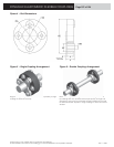
See detail drawings by part number for tolerances.
Pilot diameter tolerances are + .000/ -.005 in for -A Series
diameters and + .005/ -.000 in for -C Series diameters.
Tapered.
Refer to SAE J620c for fl ywheel numbers 6-1/2, 10, 11-1/2,
16; to SAE J927a for numbers 60, 80, 100, 120, 160. See
Tables 5 and 6.
Unless otherwise noted:
.xx dim ± 0.030 in (± 0.762 mm)
.xxx dim ± 0.015 in (± 0.381 mm)
It is advisable to refer to drawing of coupling before
ordering since it is not practical to show all details in this
catalog.
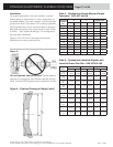
Defi nition of Part Numbering System
Part Type hp Rating
Attachment
Variation
Torsional
Stiffness
Variation
LCD -0400
-X
-XX
-A
Sure-Grip is a trademark of Altra Industrial Motion, Inc.
Torque Requirements:
Torque (lb-in) = 63025 x hp
rpm