


A part’s listing in this catalog does not guarantee its availability.
To download/print the most current catalog, go to www.lordfulfi llment.com/upload/PC7000.pdf. Rev.1 10/08
Page 119 of 124
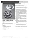
DYNAFLEX ELASTOMERIC FLEXIBLE COUPLINGS
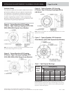
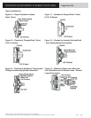
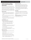
Figure 16 – Vehicle Engine with Large Angle
Drive Requirements
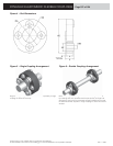
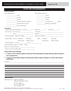
Figure 17 – Flywheel to Flanged Hub to Splined
Shaft - Free Floating Splined Connection
Figure 18 – Stationary Equipment Having a
Tapered Shaft Connection
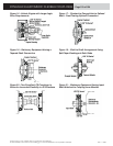
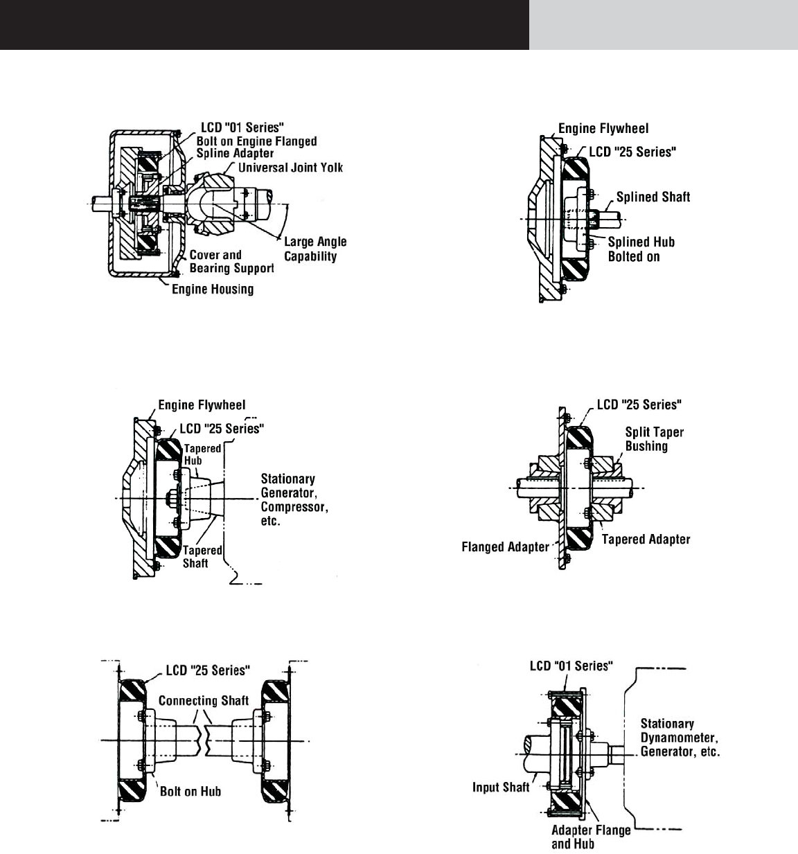
Figure 19 – Shaft to Shaft Arrangement Using
Split Taper Bushings at Both Sides
Figure 20 – Two Dynafl ex LCD Couplings in
Series for Increased Flexibility in All Directions
Figure 21 – Stationary Equipment Having Input
Shaft Attached to Coupling Inner Member