


A part’s listing in this catalog does not guarantee its availability.
To download/print the most current catalog, go to www.lordfulfi llment.com/upload/PC7000.pdf. Rev.1 10/08
Page 113 of 124
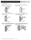
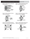
DYNAFLEX ELASTOMERIC FLEXIBLE COUPLINGS
Dynafl ex LCD Series Couplings
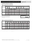
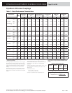
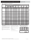
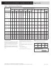
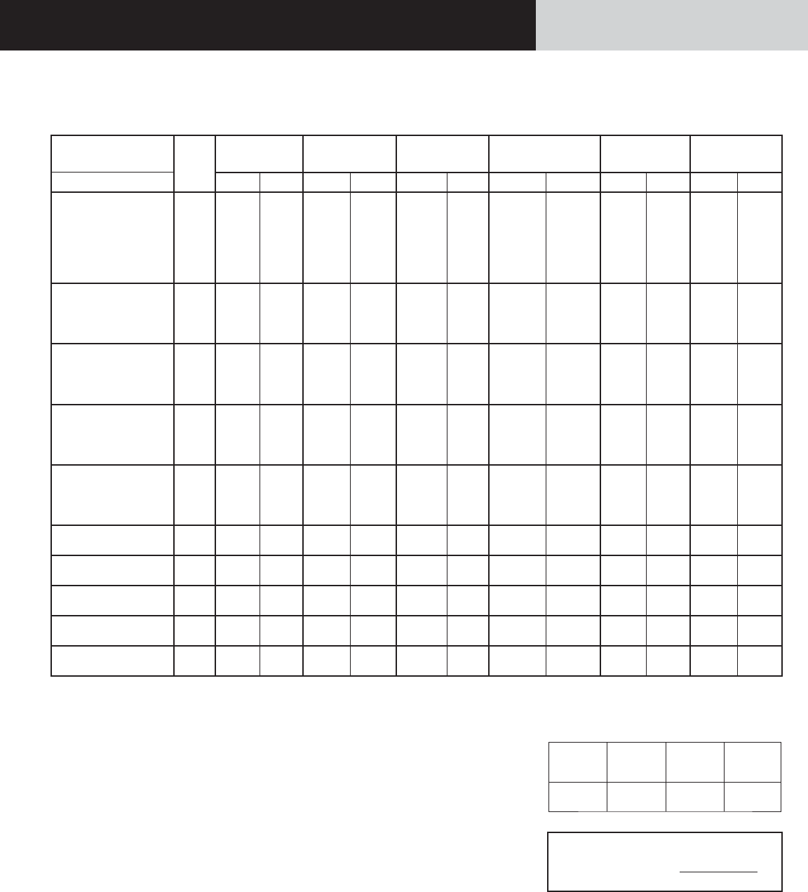
Table 2 – Rated Performance Characteristics
Part Number*
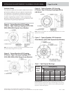
Figure
No.
Capacity per
100 rpm
Torque Rating
T
N
Approximate
Slip Torque
Torsional Rate
K
θ
Axial Rate
K
A
Radial Rate
K
R
Size
Variation
hp kW lb-in N-m lb-in N-m lb-in/rad N-m/rad lb/in N/mm lb/in N/mm
LCD-0075 -XR-A
-XXR-A
4
4
4.05 3.02 2,500 282 8,000 900 11,000 1,243 875 153 5,800 1,015
LCD-0075 -XR-C
-XXR-C
4
4
4.05 3.02 2,500 282 8,000 900 21,000 2,373 2,100 368 10,000 1,750
LCD-0075
-X-C
7 4.05 3.02 2,500 282 8,000 900 21,000 2,373 2,100 368 10,000 1,750
LCD-0150 -XR-A
-XXR-A
4
5
8.09 6.04 5,000 565 20,000 2,260 22,000 2,486 1,750 306 11,500 2,012
LCD-0150 -XR-C
-XXR-C
4
5
8.09 6.04 5,000 565 20,000 2,260 40,000 4,520 4,000 700 20,000 3,500
LCD-0200 -XR-A
-XXR-A
4
5
11.11 8.29 7,000 791 28,000 3,164 35,000 3,955 2,600 455 14,000 2,450
LCD-0200 -XR-C
-XXR-C
4
5
11.11 8.29 7,000 791 28,000 3,164 60,000 6,780 5,000 875 22,000 3,850
LCD-0300 -XR-A
-XXR-A
4
5
15.87 11.84 10.000 1,130 40,000 4,520 50,000 5,650 3,500 612 11,500 2,012
LCD-0300 -XR-C
-XXR-C
4
5
15.87 11.84 10,000 1,130 40,000 4,520 90,000 10,170 8,800 1,540 20,000 3,500
LCD-0400 -X-A
-XX-A
6
6
19.83 14.79 12,500 1,412 60,000 6,780 60,000 6,780 1,750 306 12,500 2,188
LCD-0400 -X-C
-XX-C
6
6
19.83 14.79 12,500 1,412 60,000 6,780 110,000 12,430 5,700 1,000 25,000 4,375
LCD-0600 -X-A
-X-C
6
6
31.75 23.69 20,000 2,260 85,000 9,600 100,000 11,290 1,600 280 12,500 2,188
LCD-0800 -X-A
-X-C
6
6
39.67 29.58 25,000 2,825 100,000 11,300
130,000
250,000
14,690
28,250
2,000
6.500
350
1,140
14,000
30,000
2,450
5,250
LCD-1000 -X-A
-X-C
6
6
52.91 39.47 32,000 3,616 150,000 16,950
250,000
450,000
28,250
50,850
3,250
9,000
600
1,575
20,000
35,000
3,500
6,125
LCD-1500 -X-A
-X-C
6
6
79.37 59.21 50,000 5,650 200,000 22,600
360,000
650,000
40,680
73,450
4,500
13,000
788
2,275
28,000
50,000
4,900
8,750
LCD-2000 -X-A
-X-C
6
6
103.15 77.22 65,000 7,345 200,000 22,600
675,000
1,250,000
76,275
141,250
8,500
15,000
1,488
2,625
58,000
100,000
10,150
17,500
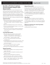
* Please consult LORD engineering for application review,
approval and availability.
Prolonged exposure to temperatures in the 0°F range and
below produces a signifi cantly reduced slip torque prior to
driveline warm-up. This condition may result in the coupling’s
inability to transmit adequate drive torque for applications
experiencing unusual cold temperature related parasitic
loading.
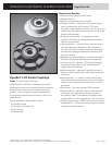
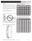
Blind assembly style with a notched periphery provides
trouble-free, sliding assembly on fl ywheel drive pins when
bolted access is not possible. Outer member is a composite
material.
Use Wood’s Sure-Grip
®
Bushing type SK or equivalent.
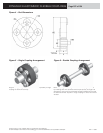
See detail drawings by part number for tolerances.
Pilot diameter tolerances are + .000/ -.005 in for -A Series
diameters and + .005/ -.000 in for -C Series diameters.
Tapered.
Refer to SAE J620c for fl ywheel numbers 6-1/2, 10, 11-1/2,
16; to SAE J927a for numbers 60, 80, 100, 120, 160. See
Tables 5 and 6.
Unless otherwise noted:
.xx dim ± 0.030 in (± 0.762 mm)
.xxx dim ± 0.015 in (± 0.381 mm)
It is advisable to refer to drawing of coupling before
ordering since it is not practical to show all details in this
catalog.
Defi nition of Part Numbering System
Part Type hp Rating
Attachment
Variation
Torsional
Stiffness
Variation
LCD -0400
-X
-XX
-A
Sure-Grip is a trademark of Altra Industrial Motion, Inc.
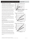
Torque Requirements:
Torque (lb-in) = 63025 x hp
rpm