


A part’s listing in this catalog does not guarantee its availability.
To download/print the most current catalog, go to www.lordfulfi llment.com/upload/PC7000.pdf. Rev.1 10/08
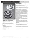
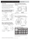
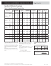
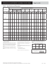
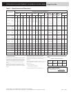
Dynafl ex LCD Series Couplings
Torsional System Analysis Input
Requirements
Dynafl ex couplings offer unique advantages with the
soft torsional spring rate that isolates torsional vibration,
mitigates shock and reduces noise transmission. In order
to benefi t from these advantages, an analysis must be
made of the application and a coupling selected which
meets the specifi c requirements. The following checklist
sets forth the information required to initiate the analysis:
Application Data
• What is the driving unit, driven unit? Include enough
information to determine disturbing frequencies
(e.g., type of engine, number of cylinders, number of
cycles).
• What is the operating torque (normal, maximum)?
• What is the operating speed (range, at normal torque
and at maximum torque)?
• What are the environmental conditions (temperature,
oil type and amount of exposure, corrosive factors,
other factors)?
Coupling Requirements
• What are the primary functions of the coupling
(torsional vibration isolation, torsional shock
mitigation, noise attenuation, shaft misalignment
accommodation – angular, parallel, axial)?
• If known, what torsional spring rate should the
coupling have?
• If the required torsional spring rate is not known, what
are the rotational moments on inertia of the driving
and driven masses?
• How much misalignment must the coupling
accommodate (angular, parallel, axial)?
• How much, if any, axial thrust will be on the coupling?
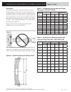
Design Parameters
• What space is available for the coupling (maximum
length, diameter)?
• What is the maximum weight the coupling can be, if
weight is limited?
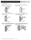
• What are the shaft diameters and method of
attachment (keyway, spline, set screws, fl ange)?
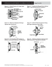
• What special features are required? (Inner member
design – hubs, fl anges, splines, etc. Outer member
design – pilot diameter bolt pattern, etc.)
Remote Driven Units
Multiple U-joint shafts (especially longer shafts) and
the speed at which the shaft rotates (especially higher
rpm’s) can create complex stability problems. To assure
satisfactory coupling performance, all design layouts
for remote mounted driven units should be reviewed
by LORD Engineering. LORD analytical capability is
only one part of the engineering service available on all
coupling applications.
What Else?
If your application is unique or unusual, include any
information that you believe will have an effect on the
coupling design or selection. If you have any questions
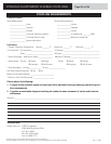
as you prepare this data, call us. See following page for
data form.
Reference Literature from Lord Corporation
Design Monograph 1107
Understanding Torsional Vibration
Page 120 of 124
DYNAFLEX ELASTOMERIC FLEXIBLE COUPLINGS