


A part’s listing in this catalog does not guarantee its availability.
To download/print the most current catalog, go to www.lordfulfi llment.com/upload/PC7000.pdf. Rev.1 10/08
Page 112 of 124
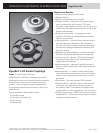
DYNAFLEX ELASTOMERIC FLEXIBLE COUPLINGS
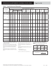
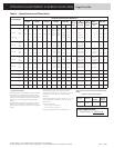
Selection Guide
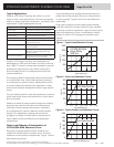
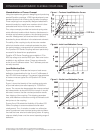
This selection guide can be used to determine the size
and series coupling to suit your general requirements.
Final selection of the specifi c coupling to satisfy all of
the application requirements generally necessitates
a system engineering analysis. These computerized
analyses of torsional systems can be provided by LORD
Corporation’s Engineering Department.
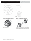
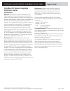
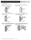
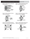
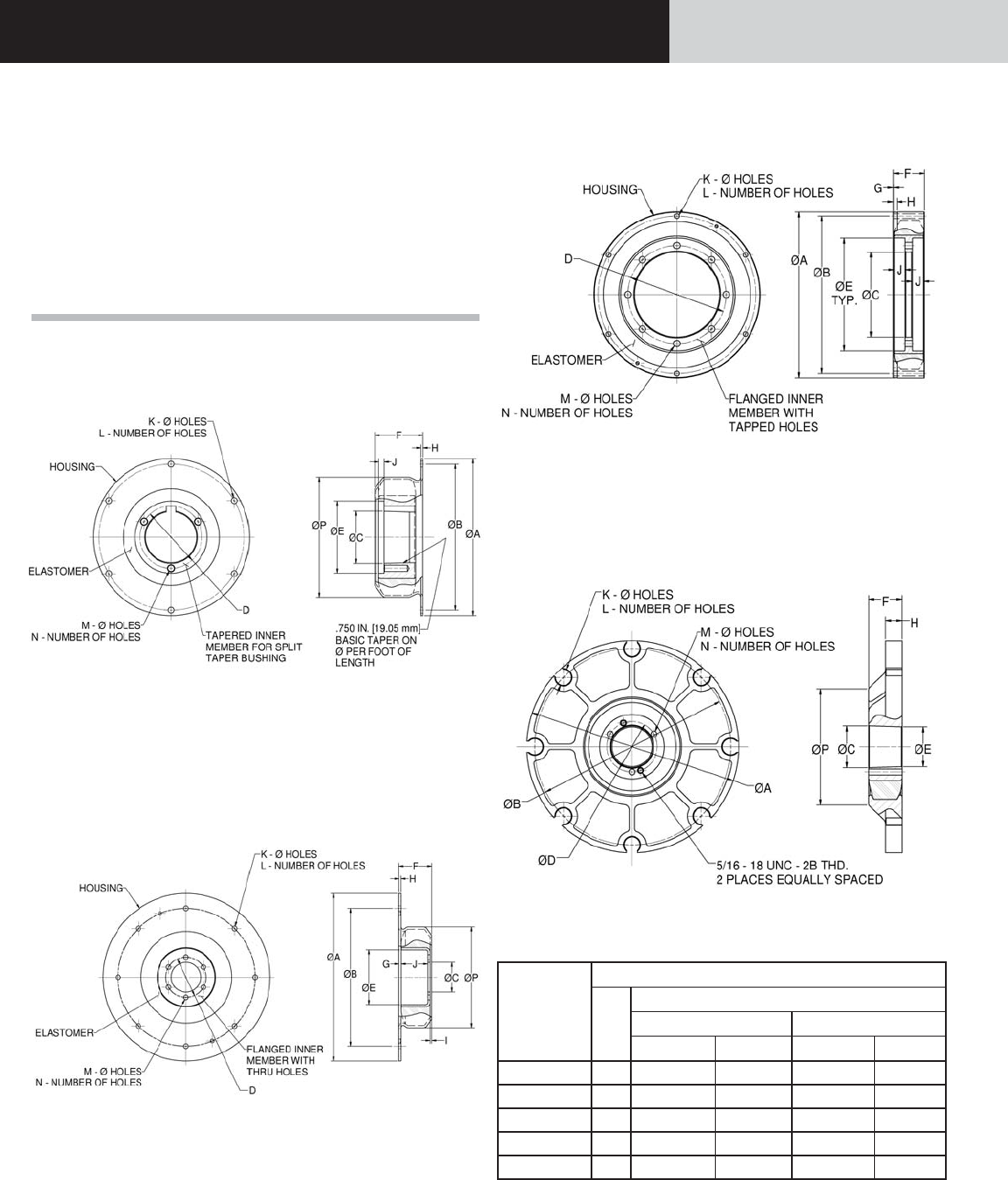
Figure 4 – Typical Dynafl ex LCD Coupling
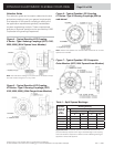
X Series - Type I Housing Couplings (0075, 0150,
0200, 0300) (With Tapered Inner Member)
Note: The LCD-0075-13 design is the same as the “20 Series” except
the outer member fl ange O.D. is very small.
Figure 5 – Typical Dynafl ex LCD Coupling
XX Series - Type II Housing Couplings (0075,
0150, 0200, 0300) (With Flanged Inner Member)
Figure 6 – Typical Dynafl ex LCD Coupling
01 Series - Type III Housing Couplings (400 hp
and above)
Note: 0400-04 has tapered inner member. 0600 and above do not have
tapered inner member.
Figure 7 – Typical Dynafl ex LCD Composite
Outer Member (0075, With Tapered Inner Member)
Dynafl ex
LCD Series
Coupling
Part
Number
Browning Bushing
P/N
Bore Range
Type 1 Dia. Type 2 Dia.
in mm in mm
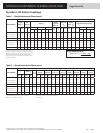
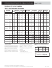
LCD-0075 Q1
3/4 - 2-1/16 19.05 - 52.3 2-1/8 - 2-11/16 54.0 - 68.3
LCD-0150-XR Q1
3/4 - 2-1/16 19.05 - 52.3 2-1/8 - 2-11/16 54.0 - 68.3
LCD-0200-XR R1
1-1/8 - 2-13/16 28.16 - 71.4 2-7/8 - 3-3/4 73.0 - 95.2
LCD-0300-XR R1
1-1/8 - 2-13/16 28.16 - 71.4 2-7/8 - 3-3/4 73.0 - 95.2
LCD-0400-XX R1
1-1/8 - 2-13/16 28.16 - 71.4 2-7/8 - 3-3/4 73.0 - 95.2
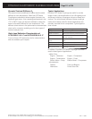
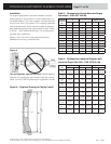
Table 1 – Split Tapered Bushings
Application Note: Sustained operation at torsional resonance can
produce vibratory torques which might cause damage to the coupling
and other driveline components. Please consult LORD Engineering for
application review and approval.