


A part’s listing in this catalog does not guarantee its availability.
To download/print the most current catalog, go to www.lordfulfi llment.com/upload/PC7000.pdf. Rev.1 10/08
Page 96 of 124
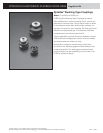
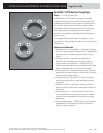
DYNAFLEX ELASTOMERIC FLEXIBLE COUPLINGS
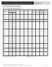
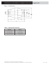
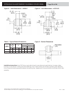
Spool Part
Number
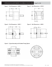
A
Diameter
B
Thickness
C
Thread
Attachement
Minimum Bolt Circle Diameter for Number of Mounts (in)
3456 7 8 9101112
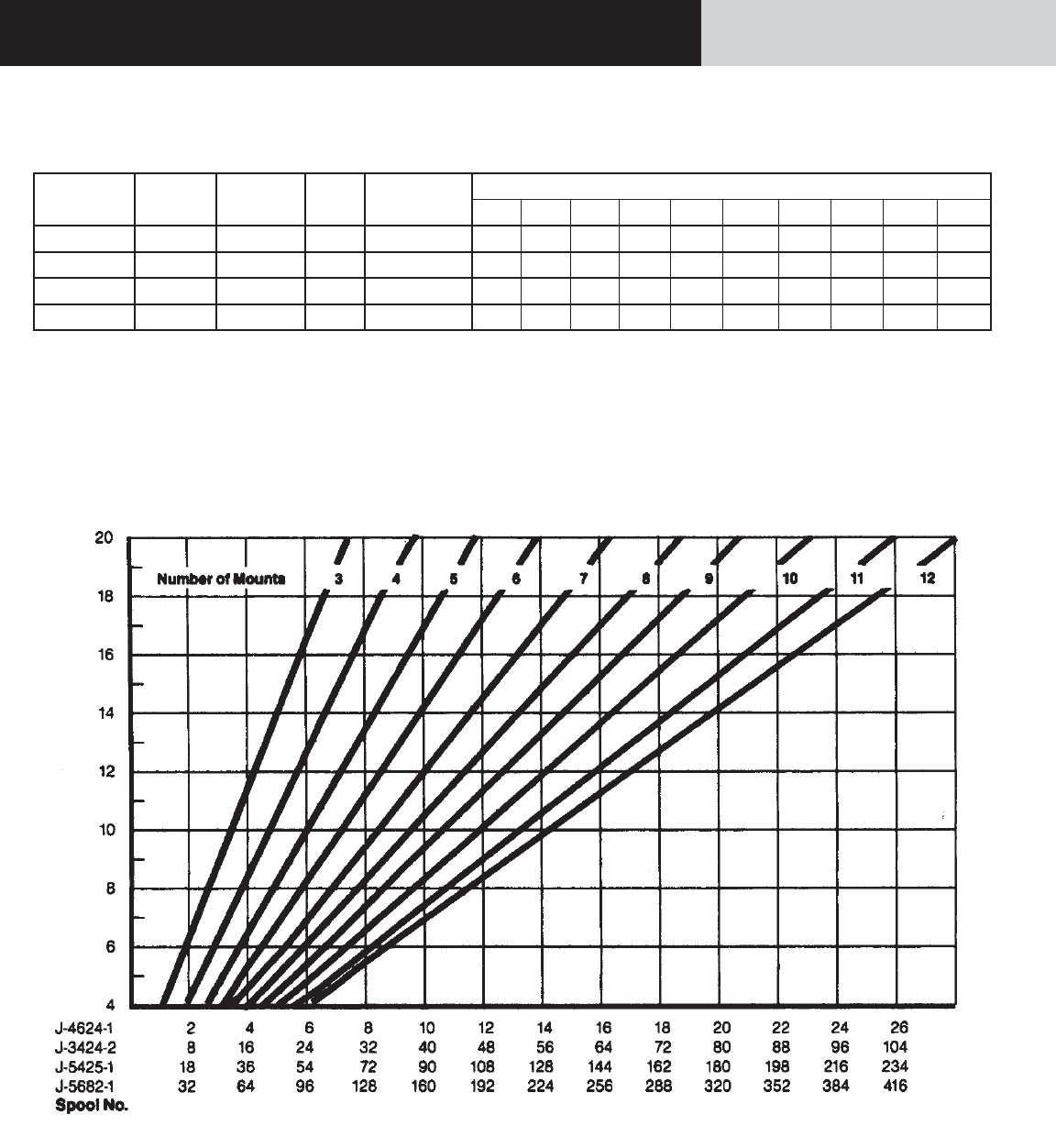
J-4624-1 1.00 0.75 0.38 1/4-20-2A 1.20 1.42 1.70 2.00 2.30 2.62 2.92 3.24 3.56 3.86
J-3424-2 2.00 2.12 0.40 1/2-13-2B 2.30 2.82 3.40 4.00 4.60 5.22 5.84 6.46 7.50 7.72
J-5425-1 3.19 3.00 1.25 1/2-13-2A 3.62 4.41 5.30 6.25 7.18 8.18 9.12 10.20 11.00 12.10
J-5682-1 4.48 2.25 1.25 1/2-20-2A 5.10 6.20 7.45 8.75 10.10 11.50 12.80 14.30 15.70 17.00
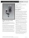
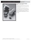
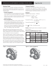
Notes: Maximum recommended misalignment - 1/32 inch parallel, 1° angular.
Coupling permits wide latitude in shaft lengths. However, suffi cient spacing between
shaft ends should be provided to allow for shaft end play.
It is suggested that all designs for Spool-Type Flexible Couplings be reviewed with
LORD Corporation.
Construction: Rubber elements - LORD does not supply hubs, elements only;
Metal parts - steel; Flexing element - environmental-resistant elastomer.
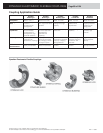
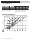
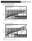
Table 2 – Coupling Confi guration Capacity Chart
Torque (lb-in x 100)
Bolt Circle Diameter (in)
Dynafl ex Spool-Type Couplings
Table 1 – Specifi cations and Dimensions