


A part’s listing in this catalog does not guarantee its availability.
To download/print the most current catalog, go to www.lordfulfi llment.com/upload/PC7000.pdf. Rev.1 10/08
Page 100 of 124
DYNAFLEX ELASTOMERIC FLEXIBLE COUPLINGS
Selection Guide
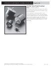
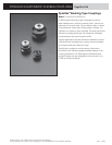
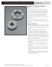
Compression bushing-type couplings are assembled
by pressing the elastomeric bushings into sockets of a
coupling fl ange. Once assembled, the coupling can be
used two ways:
• Parallel Arrangement
The driving shaft can be connected to all of the bush-
ings, and the driven shaft connected to the coupling
fl ange. This arrangement loads all bushings in parallel
and produces maximum torque capacity and a less
resilient coupling.
• Series Arrangement
This arrangement requires an even number of bush-
ings per fl ange. Mating fl anges of the driving and
driven shafts are attached to alternate bushings. This
arrangement transmits the torque through the bush-
ings in an N x N series arrangement, thereby making
the torque capacity one-half of the parallel arrange-
ment. The coupling is also more fl exible.
When high torque and small space are the control-
ling factors, the parallel arrangement is recommended.
When misalignment is the controlling factor, the bushings
should be applied in series arrangement.
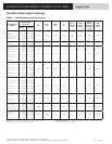
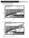
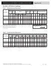
Table 1 provides selection criteria for parallel arrange-
ment, Table 2 provides data for the series arrangement.
Bushing selection is dependent upon torque require-
ments, angular, parallel and axial misalignments, as well
as bolt circle diameter, number of bushings and bushing
size. The torque values shown on the charts are nominal.
The bushings are capable of withstanding higher torques
due to the shock loads or other short duration surges.
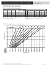
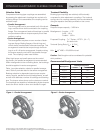
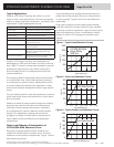
Torsional Flexibility
Bushing-type couplings are relatively stiff torsionally
compared to other elastomeric couplings. The torsional
spring rate of a coupling assembly can be calculated by
using the equation and data provided on the curves.
Example
Required torque capacity – 3400 lb-in
Misalignment – Angular – 1.75°
Axial – 1/8 in
Parallel – 1/32 in
Proposed Coupling – 7 x 7 Series, J-5737-1, (N = 7)
8 in bolt circle
Torsional Spring Rate, K
θ
= N R
2
K
R
2
K
θ
= 7 (4)
2
4000 = 224,000 lb-in/rad.
2
Caution: Shaft length must be considered for potential
whirl problems.
Recommended Misalignment Limits
Misalignment
Bushing Arrangement
Parellel Series
Single
Coupling
Angular 1° 1.75°
Parallel 1/64 in 1/32 in
Axial ±1/16 in ±1/8 in
Double
Coupling
Angular 2° 3.5°
Parallel 3/16 to 1/2 in* 3/8 to 1 in*
Axial ±1/8 in ±1/4 in
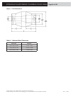
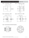
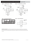
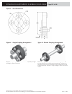
Figure 1 – Parallel Arrangement
Figure 2 – Series Arrangement
* Dependent on shaft length (10 to 30 in).