


A part’s listing in this catalog does not guarantee its availability.
To download/print the most current catalog, go to www.lordfulfi llment.com/upload/PC7000.pdf. Rev.1 10/08
Page 110 of 124
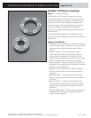
DYNAFLEX ELASTOMERIC FLEXIBLE COUPLINGS
Standardization of Proven Concept
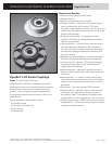
Using the experience gained in designing and producing
special Dynafl ex couplings, LORD has developed a new
standard product line of heavy-duty Dynafl ex couplings.
These couplings have a specially designed elastomeric
element bonded to a metal inner member which is then
preloaded and friction-fi t into an outer member.
This unique concept provides low torsional spring rates
which effectively isolate critical vibratory disturbances in
driveline and accessory systems, thus prolonging equip-
ment life. Misalignment and torsional shock loads are
absorbed by shear defl ection in the elastomeric element.
The ability of the coupling to slip at the outer member
with short duration shock overloads protects the drive-
line and accessory components from premature failure.
The Dynafl ex LCD Series Coupling has been particularly
successful for diesel driven applications.
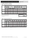
Dynafl ex LCD Series Couplings are available in 75 to
2000 hp ratings at a nominal 2000 rpm. Each size is also
available in two stiffness values. These are referred to
as the A and C stiffness values. The C stiffness parts are
normally stocked.
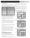
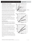
Load Defl ection Data
Figures 1 through 3 illustrate the torque or load versus
defl ection characteristics for the -A and -C stiffnesses of
the LCD-0400 size couplings. The general characteristics
of these curves are typical for all Dynafl ex LCD Series
Couplings.
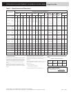
Figure 1 shows the linearity of the coupling spring rate
at (and well above) the rated capacity of 12,500 lb-in
torque. The curves also demonstrate the unique overload
slip characteristic at about 60,000 lb-in torque. It should
be noted, however, that the overload protection results
from slipping of the coupling. This slipping generates
heat, and therefore continuous running at overload could
be injurious to the coupling.
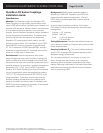
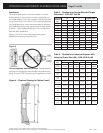
Figures 2 and 3 illustrate the fl exibility of Dynafl ex LCD
Series Couplings to accommodate axial and radial
misalignment. The -A variation is made in a softer elas-
tomer to produce a lower torsional spring rate and there-
fore had the lower axial and radial spring rates. All spring
rates are ideally linear over the normal operating range of
defl ection.
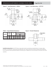
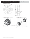
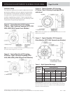
Figure 1 – Torsional Load/Defl ection Curves
Figure 2 – Axial Load Defl ection Curves
Figure 3 – Radial Load Defl ection Curves
Defl ection (in)
Load (lb)
Angular Defl ection (deg)
Torque Load (lb-in) x 000
Defl ection (in)
Load (lb)