


A part’s listing in this catalog does not guarantee its availability.
To download/print the most current catalog, go to www.lordfulfi llment.com/upload/PC7000.pdf. Rev.1 10/08
Page 122 of 124
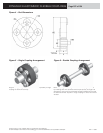
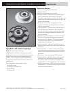
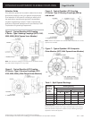
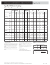
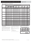
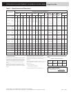
DYNAFLEX ELASTOMERIC FLEXIBLE COUPLINGS
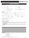
COUPLING REQUIREMENTS
Primary Function
Shaft Misalignment Specifi c Requirements
__________________Axial _______________Inches
__________________Angular _______________Degrees
__________________Parallel _______________Inches
__________________Torsional Vibration Isolation _______________% Isolation @ _________RPM
__________________Torsional Shock Loads _______________Maximum Amplitude
__________________Noise Attenuation
Parameters
* System Operating Temperature: Normal _______ °F Maximum _______ °F Minimum _______ °F
* Environment: Oil Immersion _______________________ Oil Splash ________________________________________
Other ______________________________ Mil Spec _________________________________________
* Space Envelope: Maximum Length ________________ Maximum Diameter ________________________________
* Attachments: Driving Spline Flange Driven Spline Flange
Keyways Set Screws Keyways Set Screws
* Shaft Diameters: Driving _____________ Driven ___________________
Fail-Safe Feature Required: Yes No
Maximum Allowable Weight: ___________________________
* Minimum Hours Life Required: _______________________
Please attach the following:
1. A layout of the available space envelope and other pertinent drawings showing connecting driv-
eline components.
2. A system mass-elastic diagram including all rotational mass moments of inertia and torsional
stiffnesses.
Remarks ______________________________________________________________________________________________
* Required data
Please return to: LORD Corporation
2000 West Grandview Blvd.
P.O. Box 10038
Erie, PA 16514-0038
Fax: 814 866 1773