


Operations Guide 930500E CyberData Corporation
16
Installing the VoIP V3 Indoor Intercom
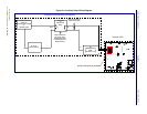
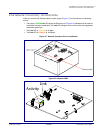
Identifying the VoIP Intercom Connectors
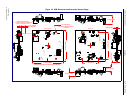
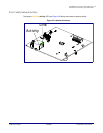
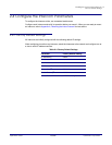
Figure 2-6. Connector Locations
Table 2-3. Connector Functions
Connector Function
J1 PoE Network Connection (RJ-45 ethernet)
J3 Terminal Block (see Figure 2-3)
J4 Factory Only—Console Port
J5 Factory Only—JTAG
JP1 Factory Only—Reset
JP5 Factory Only—Watch Dog
JP7 Factory Only—Boot Mode
JP10 Disables the intrusion sensor when installed.
J3
J1
JP1
JP5
J4
JP7
JP10 (2 Pin)
J5 (8 Pin)