


Operations Guide 930500E CyberData Corporation
15
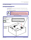
Installing the VoIP V3 Indoor Intercom
Identifying the VoIP Intercom Connectors
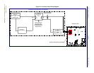
2.3.3 Identifying the VoIP Intercom Connectors
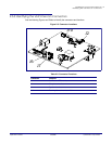
See the following Figures and Tables to identify the connectors and functions.
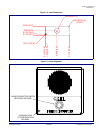
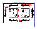
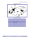
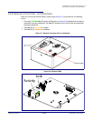
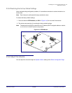
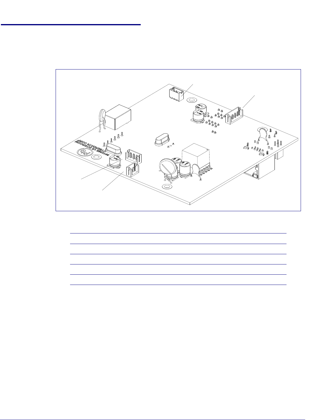
Figure 2-5. Connector Locations
Table 2-2. Connector Functions
Connector Function
J2 Call Button. LED Interface
J6 Microphone Interface
J7 Speaker Interface
J10 Proximity Sensor Interface - N/A
J2
J7
J6
J10