


Cisco IP Telephony Troubleshooting Guide for Cisco CallManager Release 3.0(1)
© 2000 Cisco Systems, Inc. 74
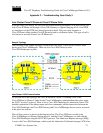
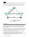
making sure the inter-cluster call can be made using H.323 version 2 protocol. Once done, the
audio path is made using the RTP protocol between Cisco IP Phones in different clusters.
Call Flow Traces
This section discusses the call flow using SDI trace examples captured in the CCM000000000
file. The location of this file can be found in the previous section. The traces discussed in this
case study focus only on the call flow itself, because the more detailed trace information has
already been explained in the previous case study (initialization, registration, KeepAlive
mechanism, and so on.)
In this call flow, a Cisco IP Phone (2002) located in Cluster 2 is calling a Cisco IP Phone (1001)
located in Cluster 1. Remember that you can follow a device through the trace by looking at the
TCP handle value, time stamp, or name of the device. The TCP handle value for the device
remains the same until the device is rebooted or goes offline.
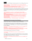
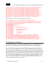
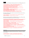
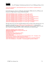
In the following traces, the Cisco IP Phone (2002) has gone off-hook. The trace shows the
unique messages, TCP handle, and the calling number, which is displayed on the
Cisco IP Phone. The called number (1001), H.225 connect, and H.245 confirm messages can be
seen in the following debug output. The codec type is G.711 µ-law.