


Cisco IP Telephony Troubleshooting Guide for Cisco CallManager Release 3.0(1)
© 2000 Cisco Systems, Inc. 50
Appendix A – Troubleshooting Case Study 1
Intra-Cluster Cisco IP Phone-to-Cisco IP Phone Calls
This case study discusses in detail the call flow between two Cisco IP Phones within a cluster,
called an intra-cluster call. This case study also focuses on Cisco CallManager and
Cisco IP Phone initialization, registration, and KeepAlive processes. That is followed by a
detailed explanation of an intra-cluster call flow. These processes are explained using trace
utilities and tools discussed in a previous section.
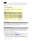
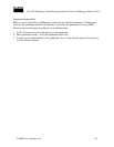
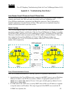
Sample Topology
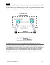
The following diagram depicts the sample topology for this case study. In the diagram there are
two clusters named Cluster 1 and Cluster 2. The two Cisco CallManagers in Cluster 1 are called
CCM3 and CCM4, while the two Cisco CallManagers in Cluster 1 are named CCM1 and CCM2.
The traces collected for this case study are from CCM1, which is located in Cluster 2. The call
flow is based on the two Cisco IP Phones in Cluster 2. The IP addresses of these two
Cisco IP Phones are 172.16.70.230 (directory number 1000), and 172.16.70.231 (directory
number 1001), respectively.
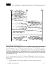
Cisco IP Phone Initialization Process
The Cisco IP Phone initialization (or “boot up”) process is explained in detail below.
1. At initialization, the Cisco IP Phone sends a request to the DHCP server to get an IP address,
DNS server address, and TFTP server name or address, if appropriate options are set in
DHCP server (Option 066, Option 150, etc). It also gets a default gateway address if set in
DHCP server (Option 003).
2. If a DNS name of the TFTP sever is sent by DHCP, then a DNS sever IP address is required
to map the name to an IP address. This step is bypassed if the DHCP server sends the IP