


Cisco IP Telephony Troubleshooting Guide for Cisco CallManager Release 3.0(1)
© 2000 Cisco Systems, Inc. 23
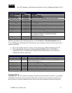
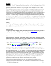
Remember that delay by itself won’t cause clipping, only variable delay will. Notice in the table
below, which represents a perfect trace, the arrival times between the audio packets (which will
have an RTP header), will be 20 ms. In a poor quality call (such as a call with a lot of jitter), the
arrival times would vary greatly.
A Perfect Trace
Packet Number Time – absolute (ms) Time – delta (ms)
1 0
2 0.02 20
3 0.04 20
4 0.06 20
5 0.08 20
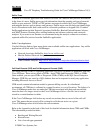
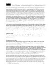
Placing the packet analyzer into various points in the network will help narrow down where the
delay is coming from. If no analyzer is available, other methods will be required. It is important
to examine interface statistics of each device in the path of the audio. Another tool for tracking
calls with poor voice quality is the Diagnostic Call Detail Records (CDRs). See the CDR section
in the Problem Categories section above, or Appendix D for more information about CDRs.
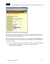
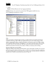
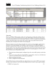
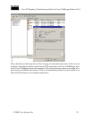
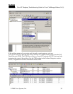
Then values for jitter and latency can be retrieved for all calls (but only after the call has
terminated). Following is a sample Diagnostic CDR (CallDetailRecordDiagnostic is the actual
table name). The number of packets sent, receive, lost, jitter, and latency are all recorded. The
globalCallID value can be used to find the call in the regular CDR table so that the disconnect
cause and other information can be obtained. The diagram below shows both tables open. Notice
that in the Diagnostic CDR, every device that can possibly report this information is included. So
if the problem is between two Cisco IP Phones, we see two table entries per call. If we have a
call through a Cisco IOS Gateway, for example, we only see the diagnostic information from the
Cisco IP Phone, not the gateway because there is no mechanism for it to notify the SQL database
with this information.