


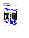
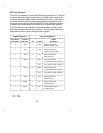

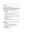

DCP Line Interface
The DCP line interface is a standard D8W 8-wire modular cord. One pair
is used for balanced digital transmission
to
the PBX switch; another pair
is used for balanced digital reception
from
the PBX switch. A third pair in
the 8-wire modular cord provides auxiliary power for the adjunct, and a
fourth pair is used only by the CALLMASTER II with Recorder Interface
to provide the analog Record Out signals to an external tape recorder.
The 8 line-jack pins are numbered in increasing order from left to right
when facing the jack with the tab slot down. The table below shows pin
assignments for the line cord and jack block interface.
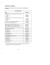
CONNECTOR BLOCK DCP JACK INTERFACE
Conn. Block D Inside Signal
Pin Number Wire Color Pin Name Description
Balance output from
telephone (power –48V)
3 W-O 1 OD1
Balance output from
telephone (power –48V)
4 O-W 2 OD2
Balance input from
PBX (power 0V)
5 W-G 3 ID1
Record output from
a CM II with Recorder Interface
1 W-BL 4 REC1
On a CM III w/o Rec. Interface)U-T*
Record output from
a CM II with Recorder Interface
2 BL-W 5 REC2
On a CM III w/o Rec. Interface)U-R*
Balance input from
PBX (power 0V)
6 G-W 6 ID2
Adjunct power –48V
(to adjunct jack)
7 W-BR 7 P1-
Adjunct power common
(to adjunct jack)
8 BR-W 8 P2+
* U-T = ‘‘Tip’’
U-R = ‘‘Ring’’
12