


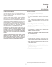

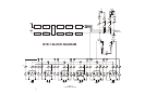
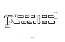
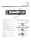
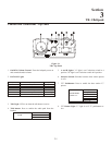
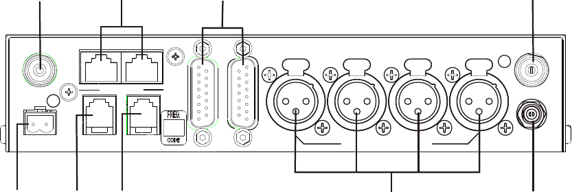
Con trols and Con nec tions - Rear Panel
12. Re lay Con tacts: Nor mally Open. When ac ti vated it will
close.
13. Re ceive An tenna Con nec tor: TNC Fe male con nec tor.
The color dot near the con nec tor must match the color of
the an tenna.
14. Aux il iary Connector: RJ-11 con nec tor used to con nect
balanced aux il iary au dio into and out of a base sta tion.
15. CAN Bus: RJ-45 con nec tors used to con nect a base sta -
tion to a CAN type of com mu ni ca tions bus.
16.
4 WIRE Con nec tor: RJ-11 con nec tor used to con nect
bal anced 4-W au dio into and out of the base sta tion.
17.
In ter com Loop Thru: Two DB15 con nec tors used to
loop 6 chan nels of in ter com au dio thru a base sta tion.
18.
In ter com Jacks: XLR in ter com jacks to al low in ter fac ing
to the first four in ter com ports via XLR con nec tors in ad -
di tion to them be ing avail able at the DB15 con nec tors.
19.
Power Con nec tor: In put power jack that re quires 12 to
15 Volts AC or DC at 1000 mA.
20.
Trans mit An tenna Con nec tor: TNC Fe male con nec tor.
The color dot near the con nec tor must match the color of
the an tenna.
2-2
ANT
CAN BUS
RCV
RELAY
AUX 4 WIRE
LOOP
THRU
Telex
TELEX COMMUNICATIONS, INC.
2 WIRE INTERCOM
1
2
3
4
TRAN
12-15V AC/DC
1 AMP
BTR-1
PATENT NO. 6,373,951 B1
MADE IN U.S.A.
13
15
17
20
12
14
16
18 19
ANT
Fig ure 2-3
BTR-1 - Rear Panel