


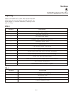

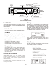
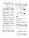
Fig ure 6-2
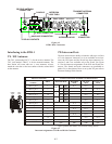
BTR-1 Rear Con nec tors
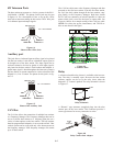
In ter fac ing to the BTR-1
TX / RX An ten nas
The TNC jack marked “RCV” is for the re ceive an tenna. The
TNC jack marked “TRAN” is for the trans mit an tenna. The
base sta tion will come with two ½ wave an ten nas. Al ways
match the color dot on the base sta tion with the col ored band
on the an tenna.
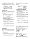
2W In ter com Ports
The base sta tion has the abil ity to in ter face with up to six lines
of 2-wire in ter com. In ter coms 1 to 4 are avail able in two lo ca --
tions, the XLR ports and the D-sub loop thru con nec tors. In --
ter coms 5 and 6 are avail able only at the D-sub. See Fig ure
6-3 for the in ter com as sign ments of the XLR and D-sub con --
nec tors. The fe male and male con nec tors are par al leled to --
gether. For a description of how to set up the 2W port re fer to
In ter com Set tings in this Sec tion.
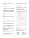
*QB= Quar ter back mode. See in ter com set ting sec tion.
Fig ure 6-3
In ter com As sign ments of XLR and D-Sub Connetors
6-3
ANT
CAN BUS
RCV
RELAY
AUX 4 WIRE
LOOP
THRU
Telex
TELEX COMMUNICATIONS, INC.
2 WIRE INTERCOM
1
2
3
4
ANT
TRAN
12-15V AC/DC
1 AMP
BTR-1
PATENT NO. 6,373,951 B1
MADE IN U.S.A.
RELAY CONTACTS
AUXILIARY CONNECTOR
4 WIRE CONNECTOR
RECEIVE ANTENNA
CONNECTOR
CAN BUS
INTERCOM
LOOP THRU
TRANSMIT ANTENNA
CONNECTOR
INTERCOM JACKS
POWER
CONNECTOR
1
8
1
8
9
9
15
15
FEMALE
D-SUB
MALE
D-SUB
Physical Connections Possible Connections when BTR-1 in Indicated Mod
XLR Number,
XLR Pin
DB-15 RTS XLR Mode
RTS DB15
Mode
2W Telex
Mode
Clear-Com
Mode
XLR 1, pin 2 1
OR
IC 1 CH 1 IC 1 IC 1+
XLR 1, pin 3 9 IC 1 CH 2 IC 1- IC 1
XLR 2, pin 2 2
OR
IC 2 CH 1 IC 2 IC 2+
XLR 2, pin 3 10 IC 2 CH 2 IC 2- IC2
XLR 3, pin 2 3
OR
IC 3 CH 1 IC 3 IC 3+
XLR 3, pin 3 11 IC 3 CH 2 IC 3- IC 3
XLR 4, pin 2 4 IC 4 IC 4+
XLR 4, pin 3 12 IC 4- IC 4
5 IC 5 IC 5+
13 IC 5- IC 5
6 IC 6 IC 6+
14 IC 6- IC 6
XLRs 1,2,3,4, pin 1 7 & 8 GND GND GND GND
15 QB* QB* QB* QB*