


Installation Installation Procedures
Revised April 2000 DBS-EX23-530 2-23
Installing ISDN in a Double Cabinet with ISDNs in the
Master and Slave
1. Before beginning ISDN installation, perform the “ISDN Function Reset”
command (FF1 9# 1# 1#).
This command must be issued before the ISDN
can be installed properly.
2. Check SW4 on the SCC-B card. Be sure it is set to “Mode B.” (See Step 2
on page 2-14.)
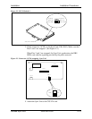
3. Install the Sync Unit in the master cabinet as described in Steps 3 and 4 on
pages 2-15 and 2-15.
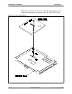
4. Install an MDF card in each cabinet. (See Step 5 on page 2-17.)
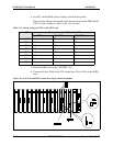
5. Set Switch 1 on the ISDN cards. (See Step 6 on page 2-18.)
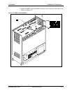
6. Install an ISDN card in each “EC/TRK” slot.
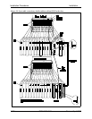
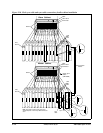
7. Connect the Clock Sync Cable from CN4 on the master-cabinet ISDN to
CN5 on the slave-cabinet ISDN, as shown in Figure 2-10.
Note: Part Number VB-43564 is used for the Clock Sync Cable when
ISDNs are installed in the master and slave cabinets.
8. At the master cabinet, connect the Sync Cable from CN1 on the Sync Unit
to CN5 on the ISDN card (Figure 2-10).
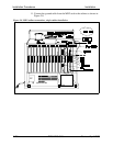
9. At each cabinet, connect the cable attached to CN3 on the MDF card to
CN3 on the ISDN card (Figure 2-8).
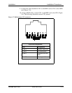
10. Using an RJ48 cable, connect CN1 of each MDF card to a CSU. (See
Figure 2-7 for RJ48 pinouts.)
11. For both cabinets, connect the ground cable from the MDF card as shown
in Figure 2-8 on page 2-20.