


Installation Installation Procedures
Revised April 2000 DBS-EX23-530 2-19
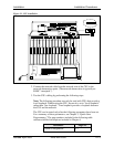
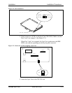
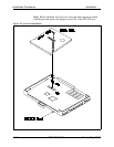
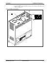
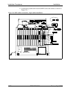
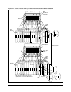
9. Connect the cable attached to CN3 on the MDF card to CN3 on the ISDN
card (Figure 2-8).
10. Using an RJ48 cable, connect CN1 on the MDF card to the CSU (Figure
2-8). The following illustration shows CN1 pinouts.
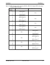
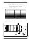
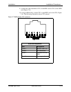
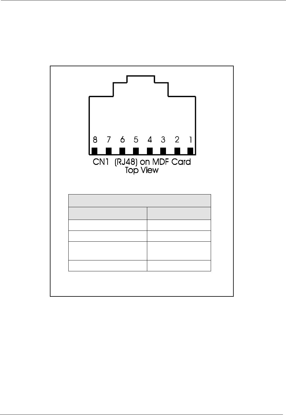
Figure 2-7. RJ48 pinouts, CN1 connector
RJ48 Pin Designations
Pins Designation
1 and 2 Receive from CSU
3 and 6 No connections
4 and 5 Transmit from the
DBS
7 and 8 Frame ground