


Installation Installation Procedures
Revised April 2000 DBS-EX23-530 2-15
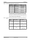
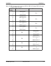
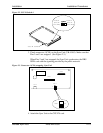
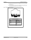
Figure 2-2. SCC-B Switch 4
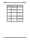
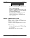
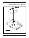
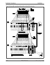
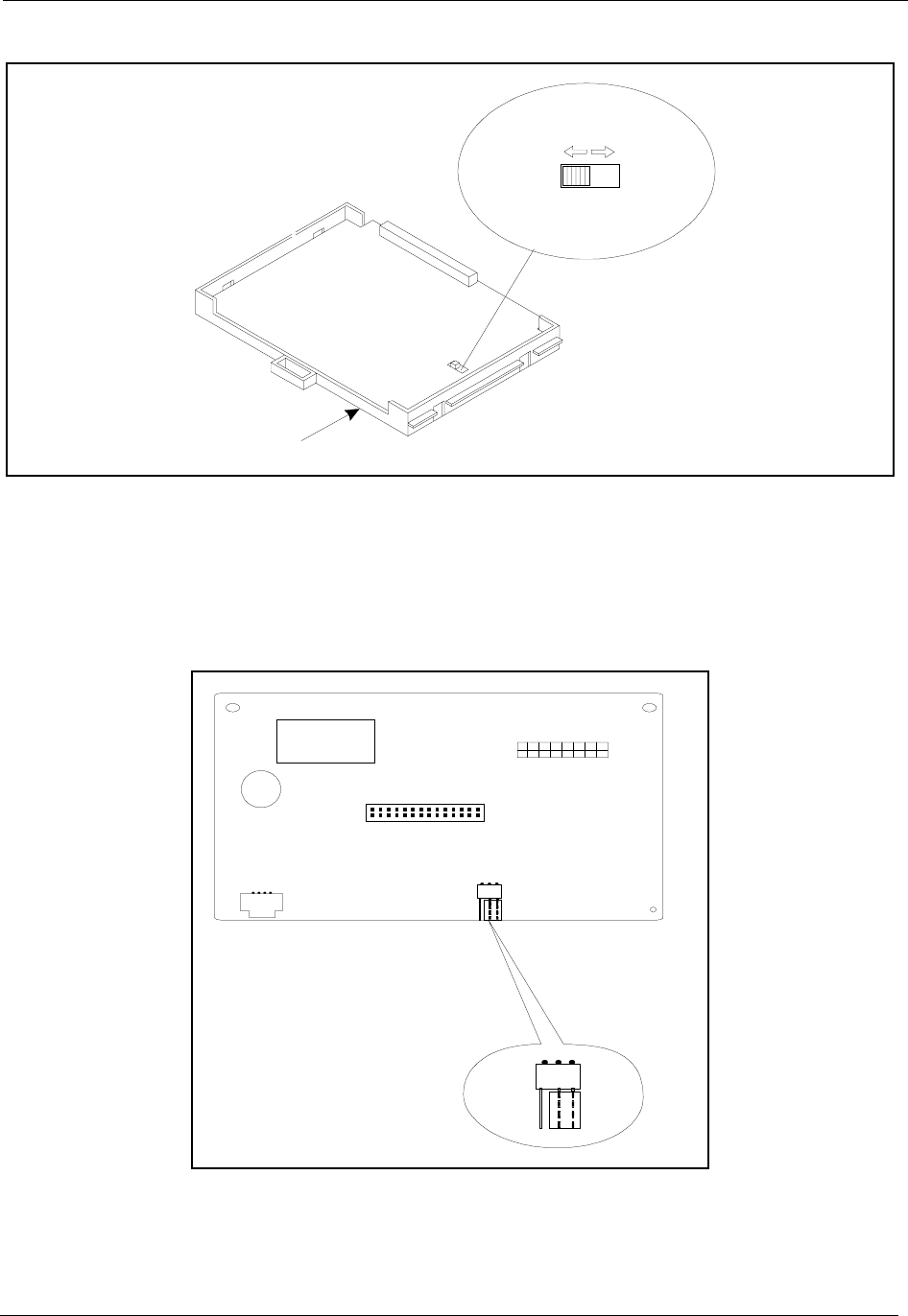
3. Check connector 4 (CN4) on the Sync Unit (VB-43563). Make sure that
Pins 2 and 3 are strapped. (See Figure 2-3.)
When Pins 2 and 3 are strapped, the Sync Unit synchronizes the DBS
ISDN card with the signaling provided by the public network.
Figure 2-3. Connector 4 (CN4) strapping, Sync Unit
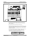
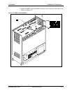
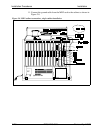
4. Attach the Sync Unit to the CPC-EX card.
(C P C -B
CPC-EX)
(CPC-A
CPC-AII)
SW 4
SCC-B Card
M ode B
ModeA
CN2
CN3
CN1
CN4
Free Net
1
3