


SP200/210 Maxon SP200/210 Radio
Issue 1.0 APPENDIX A - ACC-2003 INTERFACE BOX
03/01 Page 11-1
11 APPENDIX – ACC-2003 ALIGNMENT BOX
11.1 Purpose
This Section is reproduced from the ACC-2003 User Guide and provides information on the operation
of the ACC-2003 Interface Test Jig.
This jig is used for the Service adjustment of the SP200/210 radio.
The Calibration program (Calibration.exe) is used to allow the setting of ASIC conditions within the
radio.
Default ASIC conditions can be programmed into a radio and then repeated from radio to radio.
For non-ATE conditions, such as Repair or Adjustment, the various parameters can be manually
adjusted.
11.2 Test Equipment
A Standard Radio Communication Test Set, oscilloscope and 7.5V Power supply are required.
11.3 Calibration Program
11.3.1 Operation
Ensure that the Power Switch is OFF on the Interface box. Switch on the S200/210 and place
the volume control at the half-way position.
Place the ATE/MANUAL switch in the ATE position (switch down). Place the Audio EN switch in the
ON position (switch down) and PTT off. Switch the Test Jig on by operating the on/off switch.
The letter ‘A’ should be displayed on the SP200/210.
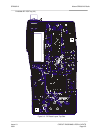
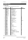
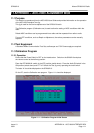
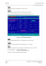
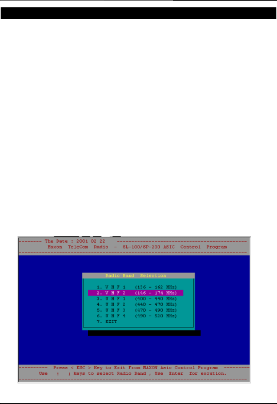
On the PC, start the Calibration.exe program. Figure 11-1 should be displayed.
Figure 11-1 – Calibration Program Initial Screen