


Maxon SP200/210 Radio SP200/210
DETAILED FUNCTIONAL DESCRIPTION Issue 1.0
Page 5-2 03/01
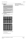
5.3 Audio ASIC
The audio ASIC (IC406) processes both the audio signal and the sub-audible tones, including filtering,
amplifying, setting attenuations levels etc. It is a programmable device, controlled by the
microcontroller, hence alteration of deviation levels is achieved by the ACC-2003 Alignment Software.
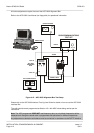
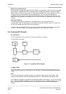
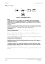
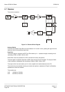
The internal block diagram is shown in Figure 5-1. The audio and SAT routes within the ASIC will be
described separately.
5.3.1 Audio Signal Path
A1 Buffers discriminator audio input from Pin 30 (INI) and passes it to
Analogue Switch 1 (ASW1). It has a gain of x1.
A2 Amplifies the analogue signal from the mic input terminal (IN2) and
passes this signal to Analogue Switch 1. It has a gain of 10dB.
ASW1 This is a two-way analogue switch. It is controlled by the serial control
interface. Default value is 0, which is Rx (A1).
INTRIM Sets the deviation for the input analogue signal sensitivity. The control
range of this device is –3.5 to +4dB controllable in 16 steps. The
control is a 4 bit signal where the default value is 1000, which
corresponds to 0dB.
300Hz HPF Comprises an 8
th
order filter with a cut-off frequency of 300Hz.
Attenuation of the unwanted is at least 30dB.
ASW2 This is a four-way analogue switch, controlled by the serial control
interface. It passes the received audio to the de-emphasis circuit or
the transmit audio to the pre-emphasis circuit. Alternatively, the pre-
emphasis or de-emphasis can be bypassed. The control signal is a 2
bit signal with 00 as the default, which is de-emphasis.
DE-EMPHASIS Applies de-emphasis to the received audio at 6dB/octave. At 1kHz, the
gain is x1.
PRE-EMPHASIS Applies pre-emphasis to the transmit audio at 6dB/octave. At 1kHz,
the gain is x1.
RXVOL Controls the magnitude of the Rx audio signal which is passed, via the
volume control (VR5) to the speaker in 16 steps from 0dB attenuation
up to 37.5dB attenuation, to Rxout on pin 28.
AMP This amplifier provides gain, to the Tx audio, in 8 steps from +20dB to
+41dB.
LIMITER Applies limiting at 0dB (2.8V p-p). The output of this stage is controlled
in 4 steps from 0dB to –5.4dB attenuation by a 2 bit control signal.
ASW3 This is a two-way analogue switch, controlled by the serial control
interface. It passes the Tx audio, or the SAT to the low-pass filter.
VLPF This is a 6
th
order low pass filter, which is controlled by the serial
control interface. The cut-off point is switched between 2.55kHz and
3kHz.
TXTRIM1 Provides deviation adjustment of Tx audio in 16 steps from +3.5dB
gain to –4dB attenuation. Uses a 4 bit control signal.
TXSUM Mixes (Adds) the signal from TXTRIM1 with the SAT signals from
COMPIN+, or selects one or other of the signals. Can also apply 50dB
muting. Controlled by the serial control interface.
ATTN Attenuates the signal from TXSUM by either 0dB or 6dB.
TXTRIM2/3 Signal follows two routes (to VCO & TCXO) for final deviation
adjustment in 32 stages from +3.75dB to –4dB. Controlled by 5 bit
signal.
A3/A4/INV Final output buffer amplifier for Tx analogue signal. Gain is 0dB. A3
output (modout 1 on pin 1) goes to the VCO and A4 (modout 2 on pin
2) goes to TCXO, are non-inverting outputs. The inverting output (INV)
from A4 is not used.