Maxon SP200/210 Radio SP200/210
INSTALLATION, COMMISSIONING & ALIGNMENT - Issue 1.0
Page 4-10 03/01
REMOVING AND REPLACING THE MAIN
ASSEMBLY
Removal
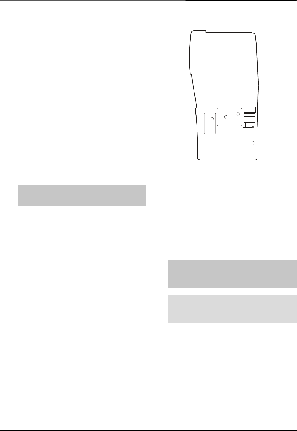
With the battery pack removed, there are four,
black, cross-head screws visible.
These can now be removed along with the
black, cross head screw holding the
accessories socket dust cover.
Unscrew the antenna and slide off the volume
control knob.
Replace the battery
but do not
push all of the
way home. Gripping the lower sides of the
battery, and the lower sides of the radio lever
the two apart at the bottom of the radio to
separate the two.
Withdraw the module from the case.
Remove the battery from the module.
This level of disassembly will be enough for
test purposes.
Note
: A screwdriver, or similar object, should
never
be used to force open the radio as the
sealing gasket is likely to be damaged.
To reassemble the radio, carry out the above
instructions in reverse, ensuring that the seal
is pushed down into the cover. Take care not
to damage the sealing gasket.
With the two parts of the radio separated, for
servicing, it will be necessary to link the two
pcbs using the flexi-pcb ME110016, which is
part of the Service Kit.
LOCATION OF ADJUSTMENT POINTS
TP1
RF PCB
L203
C208
TCXO
Figure 4-14 – Adjustment Points
4.5.3 PLL Alignment
Before any alignment is carried out to the
transmitter, or receiver, it is necessary to align
the Phase Locked Loop (PLL). The PLL
consists of the Rx VCO, Tx VCO and TCXO.
If the PLL is out of lock, an audible warning
will be heard UL will appear on the LCD
display.
Note:
This alert will also be heard when a
channel is programmed out of the range of
operation of the radio, or it is not programmed
at all.
Note
: If the power save parameter is
programmed there will be a periodic change at
TP1. Measurement should be based on the
steady state voltage, with power save off.
In order to carry out repairs, the two halves of
the radio may need to be linked using the flexi-
pcb, ME110016.
This is part of the Service Kit and the Interface
Box and leads will also be required for some
of the tests.
Connect the radio under test to the Test
Equipment.


