


SP200/210 Maxon SP200/210 Radio
Issue 1.0 TROUBLESHOOTING
03/01 Page 6-1
6 TROUBLESHOOTING
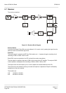
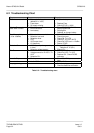
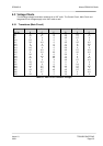
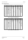
This section includes voltage and troubleshooting charts which should assist the engineer to isolate
and repair the fault. Voltage measurements should be made using a high-impedance voltmeter and
the values given are with respect to ground.
Obvious checks, such as battery performance on load, should be made before pulling the radio apart.
Substitution of another set of batteries, or the use of a power supply, isolates this cause.
The alignment procedures, given in Section 5, list how standard tests such as SINAD measurements
can be made. These can be used to check the performance of the receiver.
Careful alignment, using suitable test equipment, and quality interface cables should ensure that the
radios meet their specified performance.
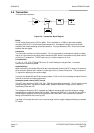
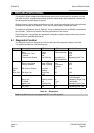
6.1 Diagnostic Function
The diagnostic function is designed to inform the user about the operational status of the radio.
The possible audible and visual warnings are:
Status Description LED Colour LCD Indication Audible Tone
Normal Power On Ready N/A 188 Melody
Busy Yellow Channel Number N/A
Correct S.A. Tone Green N/A
Transmit Red N/A
Transmit Not Allowed Red Flashing Alternating UL
with Channel No.
Repeating Dual Tone
Scanning Scan Flashing Green N/A
Priority Scan Mode Green Flashing N/A N/A
Priority Lookback Green Flashing Lb/Channel
Number
N/A
Priority
Edit
Edit Priority Channel Two Red
Flashes
PE N/A
Scan Edit Edit Scan List Single Red
Flash
SE N/A
Warning Time-Out Timer N/A Pt Single Tone/Triple
Tone Repeated
Busy Lock Flashing Yellow bL Repeating Single Tone
Tx Inhibit N/A _h/r0 Two Beeps
Battery Low Flashing Red LC Repeating Triple Tone
Error EEprom N/A Er Repeating Single Tone
PLL Error N/A UL Repeating Dual Tone
Table 6-1 – Diagnostics
Note:
All audible tones can be programmed OFF for silent operation.