


6
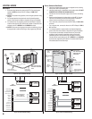
TELEPHONE WIRING
The RE-2 connects between the incoming telephone line of the
residence and local telephone sets.
Telephone Bypass Module
The RE-2’s Telephone Bypass Module provides a switch to remove
the RE-2 from the telephone line and re-connect the local telephones
to the telephone system. ALL TELEPHONE WIRING FOR THE
RE-2 MUST PASS THROUGH THE BYPASS MODULE.
The bypass module is housed in a weather-resistant enclosure and
should be located in an area that is easily accessible to the resident.
In case of system trouble, the resident can use the bypass switch to
remove the RE-2 from the telephone system.
Telephone Wiring
• DO NOT ROUTE TELEPHONE AND AC WIRING INSIDE THE SAME
CONDUIT. Route all telephone wires inside a dedicated conduit that is
at least six inches away from any AC line wiring.
• All telephone wiring must be made on the “house” side of the telephone
company’s demarcation device (the terminal block where the telephone
line connects to the residence).
• If any security system or personal alert system at the residence is
connected to the telephone line, be sure that it is connected to the line
ahead of the Telephone Bypass Module using a RJ-31X or RJ-38X
interface.
• Use only high-quality telephone wire rated for direct underground
burial. All telephone wire should be twisted-pair with a minimum size of
24 AWG.
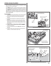
Typical Telephone Wiring
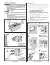
1. Connect the bypass module’s EARTH GROUND terminal to a good
earth ground.
2. Before connecting the incoming telephone line to the bypass module
check the polarity of the wires with a DC voltmeter. Connect the
negative wire (RING - usually green) to the bypass module TELCO
RING terminal. Connect the positive wire (TIP - usually red) to the
bypass module TELCO TIP terminal.
3. Connect the resident’s local telephone line RING (usually green) to
the bypass module HOUSE RING. Connect the local telephone line
TIP (usually red) to the bypass module HOUSE TIP terminal.
4. Connect the RE-2 TELCO RING to the bypass module RE-2 TELCO
RING terminal. Connect the RE-2 TELCO TIP to the bypass module
RE-2 TELCO TIP terminal.
5. Connect the RE-2 HOUSE RING to the bypass module RE-2 HOUSE
RING terminal. Connect the RE-2 HOUSE TIP to the bypass module
RE-2 HOUSE TIP terminal.
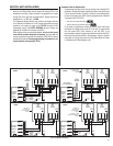
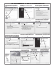
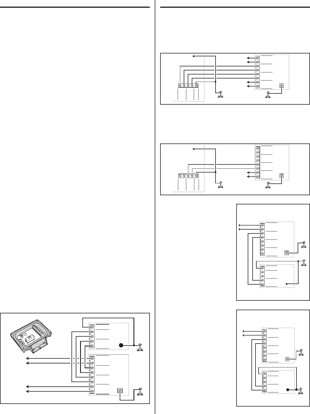
TELEPHONE WIRING OPTIONS
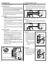
Shared Line
This is the standard confi guration. The telephone line is routed
through the RE-2 to the house phones. Pressing the Call button on
the RE-2 will cause the RE-2 to disconnect the house phones from
the telephone company line and generate a ring signal that is heard
on the house phones.
Dedicated Line
Pressing the Call button on the RE-2 will cause the RE-2 to sieze
the phone line and dial out to an outside number. See PPN #54 for
programming options.
Intercom Mode
Pressing the Call button on
the RE-2 will cause the RE-2
to generate a ring signal as
if it were an intercom station.
A live phone line is not used
and the RE-2 provides power
for the remote intercom phone.
See PPN #52 for programming
options.
✦ Note: in this mode, remote
programming, call forwarding
or alternate resident calling is
not available.
Ring Down Mode
Pressing the Call button
on the RE-2 will cause the
RE-2 to sieze the phone
line and provide immediate
communications with the PBX
system. See PPN #54 for
programming options.
TELCO
RING
TIP
RING
TIP
EARTH
HOUSE
TIP
RING
TIP
RING
TIP
RING
TIP
RING
TELCO
RE-2
TELCO
RE-2
HOUSE
HOUSE
TELEPHONE
BYPASS
MODULE
EARTH
GROUND
FROM
TELEPHONE
COMPANY
GROUND
STAKE
10' MAXIMUM
WIRE RUN
GROUND
STAKE
10' MAXIMUM
WIRE RUN
RE-2
ENTRY
SYSTEM
CASE
GROUND
GROUND
STAKE
TIP
RING
TIP
RING
TIP
RING
TIP
RING
TELCO
RE-2
TELCO
RE-2
HOUSE
HOUSE
TELCO
RING
TIP
RING
TIP
EARTH
HOUSE
TELEPHONE
BYPASS
MODULE
EARTH
GROUND
TO HOUSE
INTERCOM
TELEPHONES
RE-2
ENTRY
SYSTEM
CASE
GROUND
GROUND
STAKE
TO
PBX
SYSTEM
GROUND
STAKE
GROUND
STAKE
TIP
RING
TIP
RING
TIP
RING
TIP
RING
TELCO
RE-2
TELCO
RE-2
HOUSE
HOUSE
TELEPHONE
BYPASS
MODULE
EARTH
GROUND
TELCO
RING
TIP
RING
TIP
EARTH
HOUSE
RE-2
ENTRY
SYSTEM
CASE
GROUND
TELCO
RING
TIP
RING
TIP
EARTH
HOUSE
TIP
RING
TIP
RING
TIP
RING
TIP
RING
TELCO
RE-2
TELCO
RE-2
HOUSE
HOUSE
TELEPHONE
BYPASS
MODULE
EARTH
GROUND
TO HOUSE
PHONES
TO TELCO
LINE
GROUND
STAKE
10' MAXIMUM
WIRE RUN
GROUND
STAKE
10' MAXIMUM
WIRE RUN
RE-2
ENTRY
SYSTEM
CASE
GROUND
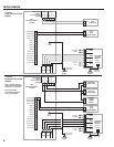
Figure 7. Dedicated Line Wiring
Figure 6. Shared Line Wiring
Figure 8. Intercom Mode Wiring
Figure 9. Ring Down Mode Wiring
Figure 5. Telephone Wiring
GROUND
STAKE
TIP
RING
TIP
RING
TIP
RING
TIP
RING
TELCO
RE-2
TELCO
RE-2
HOUSE
HOUSE
TELCO
RING
TIP
RING
TIP
EARTH
HOUSE
TELEPHONE
BYPASS
MODULE
EARTH
GROUND
TO HOUSE
PHONES
TO TELCO
LINE
RE-2
ENTRY
SYSTEM
TELEPHONE
BYPASS
MODULE
CASE
GROUND
GROUND
STAKE