


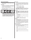
3
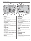
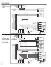
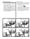
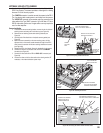
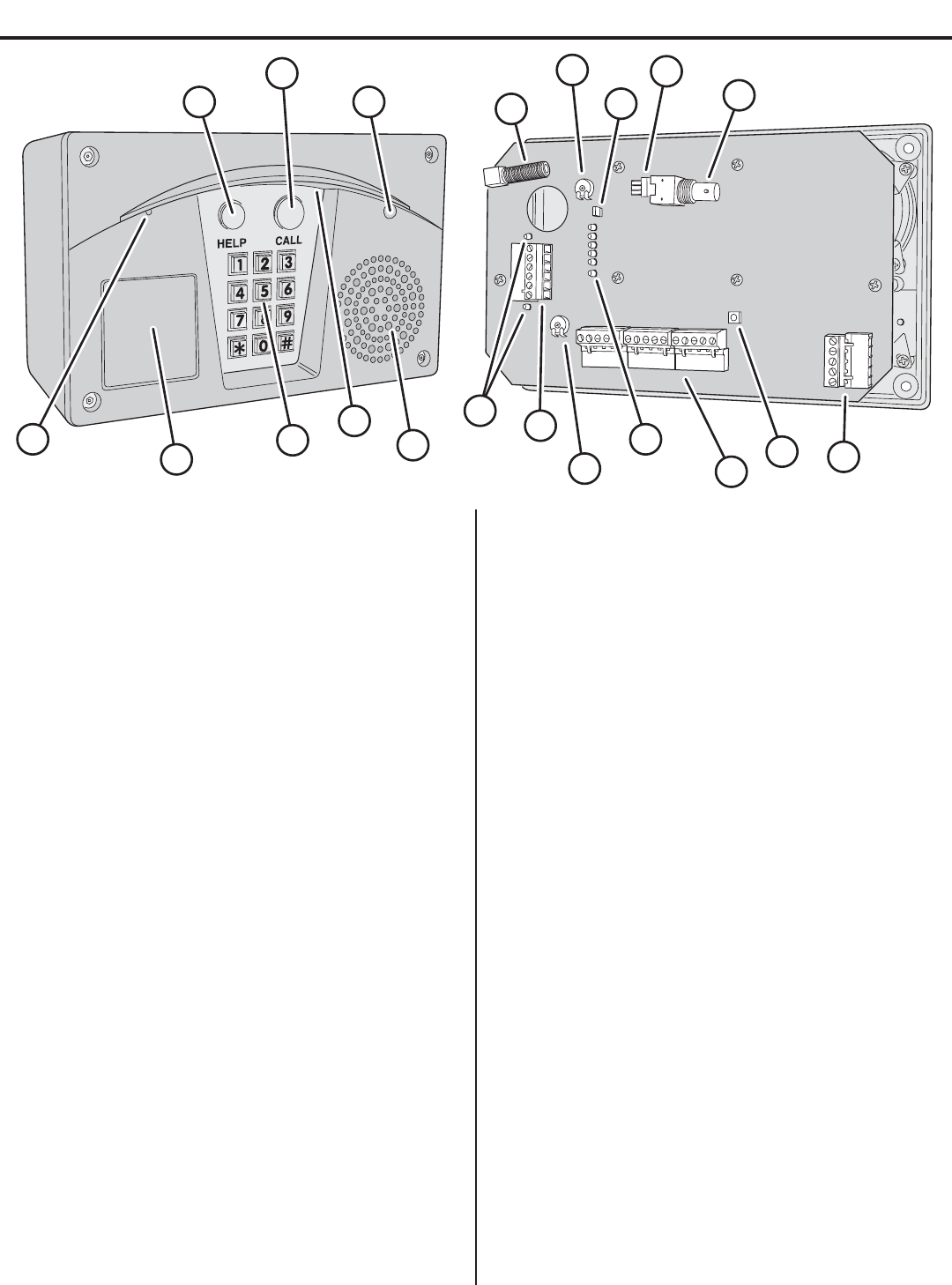
11 MAIN TERMINAL BLOCK
For power, backup battery, sense inputs, open request inputs, and
remote keypad connections.
12 STATUS INDICATORS
Six indicators light to display system power, radio, and modem
status.
13 SPEAKERPHONE VOLUME CONTROL
Controls the audio level produced by the speaker during
communications between the visitor and the resident.
14 RELAY TERMINAL BLOCK
For Relay #1 and Relay #2 output connections to the access control
devices.
15 RELAY INDICATORS
Indicators for Relay #1 and Relay #2 will light when the relay is
activated.
16 SPEAKER
Weatherproof speaker for system operation and programming.
17 DOWNLIGHT
Illuminates keypad and visitor operation buttons. The light operates
dusk to dawn and adjusts its time depending on the system’s
geographic location.
18 KEYPAD
Die-cast metal 12-key keypad with tactile action. For system
programming and keying in entry codes.
19 OPTIONAL KEYLOCK
Location for mounting access keylock.
20 MICROPHONE
The high-sensitivity microphone monitors sound at the keypad area
for the entry system’s speakerphone.
1 HELP BUTTON
Pressing this button causes the system to play the help message to
instruct the visitor on system use.
2 CALL BUTTON
Pressing this button causes the system to call the residence
telephones with a distinctive ring signal.
3 OPTIONAL COLOR CCTV CAMERA
Location for the optional Model CCM-2 color CCTV camera. The
camera views the keypad area.
4 ANTENNA CONNECTOR
For connection to a Model EXA-1000 or EXA-2000 remote
antenna.
5 DIGITAL SPEECH VOLUME CONTROL
Controls the audio level of the voice synthesizer. This adjustment
effects the audio level of the voice synthesizer and system tone from
the speaker.
6 LINE MONITOR JUMPER
For testing and troubleshooting. Remove jumper to listen to
telephone line audio through the speaker.
7 CAMERA CONNECTOR
Provides power and video connection for the optional Model CCM-2
CCTV camera.
8 VIDEO OUT CONNECTOR
For cable connection to a video monitor. (Optional Model CCM-2
CCTV camera required).
9 TELEPHONE TERMINAL BLOCK
For telephone line and earth ground connections.
10 RESTART BUTTON
Pressing this button restarts the system. This button DOES NOT
erase any programming data.
1
2
3
4
5
6
7
8
9
10
11
12
13
14
15
16
17
18
19
20
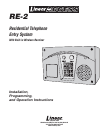
COMPONENT LOCATIONS