


9
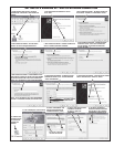
POWER, BATTERY, & GROUND WIRING
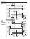
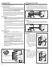
Power Wiring
✦ NOTE: DO NOT APPLY POWER UNTIL THE INSTALLATION IS
COMPLETE.
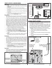
1. Route two wires between the RE-2 and the power transformer.
• For power wire runs up to 100 feet, use 18 AWG, THHN 600-volt
insulated wire.
• For power wire runs up to 200 feet, use 16 AWG, THHN 600-volt
insulated wire.
2. Connect the wires to the transformer. Connect the other end of the
wires to the two RE-2 TRANSFORMER terminals.
Backup Battery
Use of battery backup is optional. It will allow the RE-2 to operate for
short periods of time without AC power. Two 12-volt backup batteries
in series are recommended to obtain the proper working voltage
for the RE-2. A single 12-volt battery can be used, although the call
waiting beeps and the ring voltage will be lower than normal when fi ve
telephones are connected. The door or gate access device must use
some type of battery backup for the entire system to be functional.
Backup batteries will not fi t into the RE-2 housing. Protect the backup
batteries inside a rain-tight NEMA enclosure suitable for the installation.
✦ NOTE: Backup batteries are not required to maintain the RE-2 clock/
calendar and programming memory during power outages.
1. Route two wires between the RE-2 and the backup batteries.
2. Connect two 1.2 Amp/hour (minimum), 12-volt, gel cell batteries in
series (Battery #1 negative to Battery #2 positive).
3. Connect the Battery #1 positive to the RE-2 BATTERY POSITIVE terminal.
4. Connect the Battery #2 negative to the RE-2 BATTERY NEGATIVE
terminal.
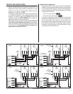
✦ NOTE: The RE-2 does not supply battery charging current. An
external battery charger will be required to maintain the batteries.
Earth Ground
For the best ground, use size 12 gauge solid wire or larger to connect
to an 8-foot copper ground rod. Locate the ground rod next to the
Power and Telephone company rods and bond the rods together
with a new clamp. Do not disturb the clamps installed by the Power
or Telephone Company. Alternately, connect to a cold water pipe for
the earth ground.
1. Connect the wire from the earth ground to the rear case ground stud.
2. Connect the Telephone Bypass Module EARTH GROUND terminal to
the earth ground wire.
3. Connect the RE-2 EARTH terminal to one of the case ground studs
(this connection is mandatory for lightning protection).
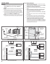
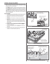
Case Ground
A ground wire connects the front and rear cases together. Be sure
to re-connect this wire before completing the installation. Refer to
Figure 15 for case ground wire attachment details.
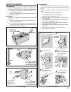
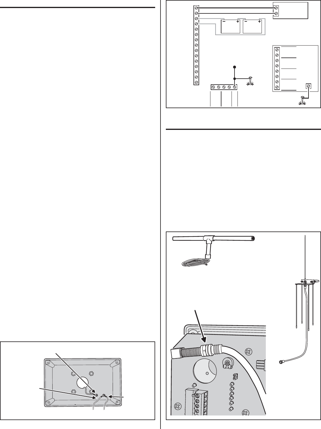
OPTIONAL REMOTE ANTENNA
If wireless transmitters are going to be used, a remote antenna must
be installed to provide reception for the RE-2.
Two models of antennas are compatible with the RE-2. The
Model EXA-1000 is a omni-directional antenna. The Model EXA-2000
is a directional antenna used in installations where transmitted
signals are desired to be received only in a particular direction.
✦ NOTE: Up to 50 feet of type RG-59 coax can be used to connect the
antenna to the RE-2. Keep the coax as short as possible.
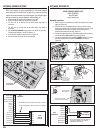
1. Install the antenna. (See EXA-1000 or EXA-2000 installation
instructions.)
2. Connect the antenna coax cable to the antenna and route the cable to
the RE-2.
3. With the power off, connect the cable to the RE-2’s ANTENNA
connector.
RE-2
TRANSFORMER
TELCO
OPEN #1
KEYPAD GND
KEYPAD DAT 1
KEYPAD DAT 0
KEYPAD PWR
TRANSFORMER
TRANSFORMER
BATTERY NEGATIVE
BATTERY POSITIVE
SENSE #1
COMMON
KEYPAD CLK
KEYPAD DVAL
OPEN #2
RE-2
TERMINALS
SENSE #2
GROUND
STAKE
RING
TIP
RING
TIP
EARTH
HOUSE
NOTE: BACKUP BATTERIES
WILL REQUIRE AN
EXTERNAL CHARGER
TIP
RING
TIP
RING
TIP
RING
TIP
RING
TELCO
RE-2
TELCO
RE-2
HOUSE
HOUSE
TELEPHONE
BYPASS
MODULE
EARTH
GROUND
12 VOLT
1.2 AMP/HR
BATTERY
12 VOLT
1.2 AMP/HR
BATTERY
NOTE: TWO 12-VOLT BATTERIES ARE
RECOMMENDED, ALTHOUGH ONE
12-VOLT BATTERY CAN BE USED
GROUND
STAKE
CASE
GROUND
Figure 16. Power, Backup Battery & Ground Wiring
CONNECT COAX
TO ANTENNA
CONNECTOR
RE-2
CIRCUIT BOARD
OPTIONAL
EXA-2000
DIRECTIONAL
ANTENNA
OPTIONAL EXA-1000
OMNI-DIRECTIONAL
ANTENNA
Figure 17. Remote Antenna ConnectionFigure 15. Case Ground Connection
CONNECT INCOMING EARTH GROUND WIRE TO ONE
REAR CASE GROUND STUD WITH A RING TERMINAL
CONNECT THE FRONT
CASE GROUND WIRE
TO THE OTHER REAR
CASE GROUND STUD
CONNECT THE
CIRCUIT BOARD
EARTH GROUND
TERMINAL TO
A CASE GROUND
STUD
IMPORTANT! FOR THE BEST PROTECTION AGAINST LIGHTNING DAMAGE
ALL EARTH GROUND CONNECTIONS MUST BE WIRED AS SHOWN