


5
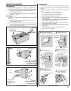
ENTRY SYSTEM MOUNTING
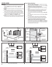
Pedestal Mounting
The RE-2 Entry System can be mounted with the Model GNC-1
(curb mount) or Model GNB-1 (burial mount) gooseneck pedestals.
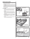
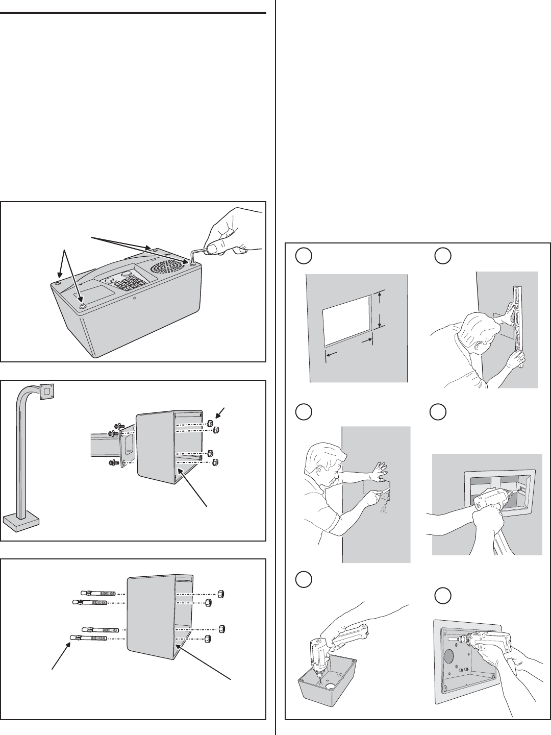
1. Open the RE-2 case by removing the four security screws with the
wrench provided (see Figure 1).
2. Use four security bolts and locking nuts to secure the backplate to the
pedestal (see Figure 2).
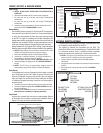
Wall Mounting
The RE-2 Entry System can be mounted directly to a wall or fl at
surface.
1. Open the RE-2 case by removing the four security screws with the
wrench provided (see Figure 1).
2. Use the appropriate fasteners to secure the system’s backplate to the
mounting surface. When mounting the system to a concrete wall, use
concrete wedge anchors (see Figure 3).
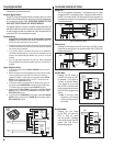
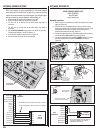
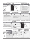
Recessed Mounting
The RE-2 can be mounted recessed using an accessory trim-ring.
The trim-ring mounts in the wall and the cabinet attaches to the
trim-ring.
Two trim-rings models are available to match the color of the RE-2
case:
• For the RE-2N use trim-ring P/N ACP00915.
• For the RE-2SS use trim-ring P/N ACP00917.
1. Identify the location of any studs in the wall.
2. Cut a 10-1/4” wide by 6-1/4” high rectangular hole between studs at
the mounting location.
3. Install any additional mounting material required to provide surfaces
inside the wall for attaching the trim-ring.
4. Place the trim-ring in the wall hole. Check for level, then attach the
trim-ring with screws into the side tabs.
5. Drill the cabinet’s four self-drill mounting holes the appropriate size for
the hardware.
6. Attach the cabinet to the trim-ring using self-tapping screws.
7. Route the wiring into the cabinet.
Figure 3. Wall Mounting
Figure 2. Pedestal Mounting
REMOVE THE FOUR
SECURITY SCREWS
TO OPEN THE CASE
Figure 1. Opening the RE-2 Case
PEDESTAL
MOUNTING
MOUNT REAR CASE
WITH SECURITY BOLTS
AND LOCKNUTS
PEDESTAL
CAUTION!
BE SURE THE MOUNTING HARDWARE
DOES NOT EXTEND MORE THAN 1"
INSIDE THE REAR COVER OR
ELECTRICAL DAMAGE MAY OCCUR
USE WEDGE ANCHORS
FOR CONCRETE OR
OTHER APPROPRIATE
ANCHORS FOR DIFFERENT
MATERIALS
WALL
MOUNTING
CAUTION!
BE SURE THE MOUNTING HARDWARE
DOES NOT EXTEND MORE THAN 1"
INSIDE THE REAR CASE OR
ELECTRICAL DAMAGE MAY OCCUR
10-1/4"
6-1/4"
MARK HOLE LOCATION
4
INSTALL ANY SPACER
SHIMS TO ALLOW MOUNTING
ATTACH THE TRIM-RING
WITH SCREWS
5
6
DRILL 3/16" HOLES IN
THE CABINET AT THE
PRE-MARKED LOCATIONS
ATTACH THE CABINET TO
THE TRIM-RING WITH
SELF-TAPING SCREWS
DETERMINE LOCATION FOR
THE 10-1/4" x 6-1/4" MOUNTING HOLE
3
CUT MOUNTING HOLE
1 2
RECESSED
MOUNTING
Figure 4. Recessed Mounting