


11
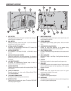
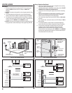
OPTIONAL COLOR CCTV CAMERA
Linear’s Model CCM-2 CCTV camera can be installed inside the
RE-2 Entry System. The camera provides a video signal for viewing
the area in front of the entry system.
The CAMERA connector is used to connect the camera to the RE-2.
The 4-conductor cable routes power to, and video from the camera.
The VIDEO OUT connector is the camera output for connection to a
video cable with a Type “BNC” connector. Up to 400 feet of 75-ohm
RG-59 video cable can be used. Longer cable runs may require the
use of a video amplifi er.
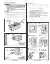
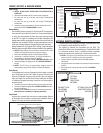
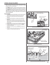
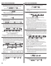
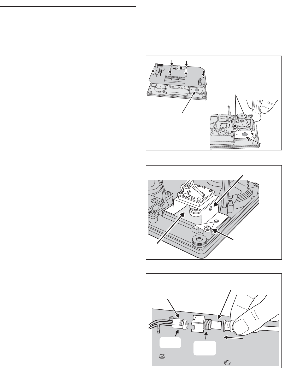
Camera Installation
1. To access the camera mounting location, remove the six circuit board
retaining screws and swing the circuit board up (see Figure 24).
2. Remove the two retaining screws and retaining brackets (see
Figure 24).
3. Carefully peel off the black dot on the plastic camera gasket (see
Figure 24).
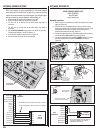
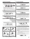
4. Mount the camera assembly on the two mounting posts, with the
alignment hole in the camera bracket towards the edge of the RE-2
case. Secure the camera with the two retaining brackets and screws
(see Figure 25).
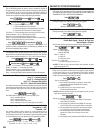
5. Replace the RE-2 circuit board. Secure the board with the six screws.
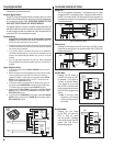
6. Connect the camera’s 4-conductor cable to the RE-2’s CAMERA
connector (see Figure 26).
7. Connect the video cable to the RE-2’s VIDEO OUT connector (see
Figure 26).
8. Connect the other end of the video cable to the viewing monitor, RF
modulator, or the video distribution system input.
REMOVE THE SIX CIRCUIT
BOARD RETAINING SCREWS
AND FLIP THE CIRCUIT BOARD UP
REMOVE THE TWO RETAINING
SCREWS AND BRACKETS
REMOVE THE
BLACK DOT
ON CAMERA
GASKET
CAMERA
MOUNTING
AREA
Figure 24. Preparing to Mount the Camera
MOUNT THE CAMERA
WITH THE BRACKET
HOLE ON THIS SIDE
SECURE THE CAMERA
WITH THE TWO RETAINING
BRACKETS AND SCREWS
PLASTIC
CAMERA
GASKET
Figure 25. Installing the Camera
CONNECT THE VIDEO CABLE FROM
THE MONITOR OR MODULATOR TO
THE RE-2'S VIDEO OUTPUT CONNECTOR
CONNECT THE CAMERA'S
CABLE TO THE RE-2'S
CAMERA CONNECTOR
CAMERA
CONNECTOR
VIDEO
OUTPUT
CONNECTOR
Figure 26. Connecting the Camera Cable and Video Cable