


8
CONTROL WIRING
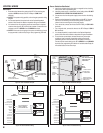
Gate Control
1. Route two wires between the gate and the RE-2. Connect the gate
operator’s OPEN terminals to the RE-2 Relay #1 COM & N.O.
terminals.
✦ NOTE: For operator wiring specifi cs, refer to the gate operator’s wiring
diagram.
2. If an access keyswitch is required refer to the Optional Keyswitch
section of this manual for details on keyswitch wiring and installation.
3. If an external timer for preventing access at certain times is required,
route two wires from the RE-2 to the timer contacts. Connect the timer
contacts to the RE-2 SENSE #1 and COMMON terminals.
✦ NOTE: If the sense input is going to be used as an inhibit input, it must
be programmed to select that input type. See programming PPN #29.
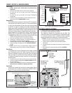
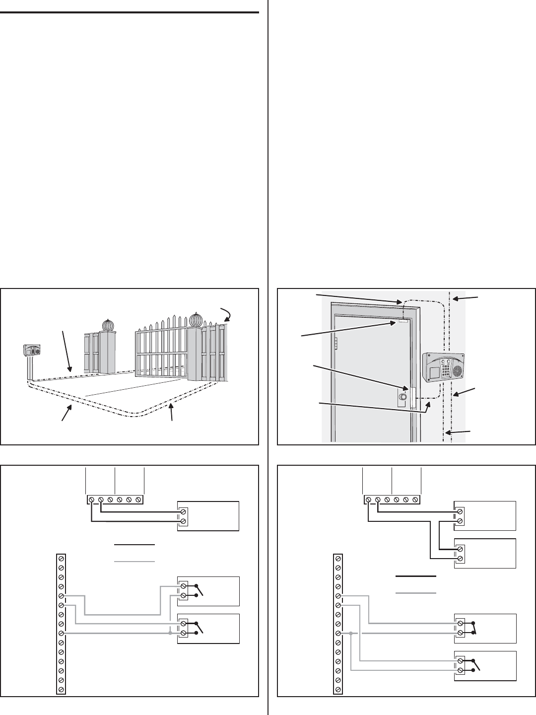
Door or Pedestrian Gate Control
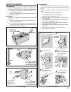
1. Install a low voltage electric door strike or magnetic lock as a locking
device for the door or pedestrian gate.
2. Install the power supply or transformer for the locking device. DO NOT
POWER THE RE-2 FROM THIS POWER SUPPLY.
3. Connect one wire from the power supply to one wire from the locking
device.
4. Route two wires between the locking device and the RE-2. Connect
one wire to the remaining wire of the locking device. Connect the
other wire to the remaining wire of the power supply.
• For a door strike, connect the wires to the RE-2 Relay #1 COM & N.O.
terminals.
• For a magnetic lock, connect the wires to the RE-2 Relay #1 COM &
N.C. terminals.
5. If an access keyswitch is required refer to the Optional Keyswitch
section of this manual for details on keyswitch wiring and installation.
6. To use the door sense feature to detect forced entry or door ajar
conditions, install a normally closed door switch on the door or
pedestrian gate and route two wires from the switch to the RE-2.
Connect the door sense switch to the RE-2 SENSE #1 and COMMON
terminals. See programming PPN #24 & #27 to defi ne when Relay #2
will activate based on the sense input.
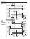
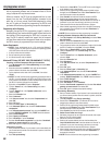
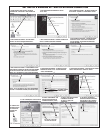
Figure 12. Gate Installation Wiring
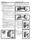
Figure 13. Door Installation Example
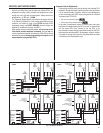
Figure 11. Gate Installation Example
Figure 14. Door Installation Wiring
DOOR
SENSE
SWITCH
ACCESS
KEYSWITCH
OPEN #1
KEYPAD GND
KEYPAD DAT 1
KEYPAD DAT 0
KEYPAD PWR
TRANSFORMER
TRANSFORMER
BATTERY NEGATIVE
BATTERY POSITIVE
SENSE #1
COMMON
KEYPAD CLK
KEYPAD DVAL
OPEN #2
RELAY
#1
RE-2
TERMINALS
SENSE #2
OPTIONAL WIRING
REQUIRED WIRING
N.O.
COM
N.C.
N.O.
COM
N.C.
RELAY
#2
ELECTRIC
DOOR STRIKE
DOOR STRIKE
POWER SUPPLY
2 WIRES FOR DOOR
STRIKE POWER FROM
POWER SUPPLY
DOOR
SENSE
SWITCH
ELECTRIC
DOOR
STRIKE
RE-2
ENTRY
SYSTEM
2 WIRES
FOR DOOR
STRIKE
2 WIRES
FOR DOOR
SENSE
SWITCH
2 WIRES FOR RE-2
POWER FROM
TRANSFORMER
4 WIRES FOR
TELEPHONE
NOTE: ROUTE TELEPHONE
WIRES AWAY FROM
POWER WIRES
RE-2
ENTRY
SYSTEM
2 WIRES FROM
TRANSFORMER
FOR RE-2 POWER
GATE
OPERATOR
(BEHIND GATE)
2 WIRES FROM RE-2
TO GATE OPEN TERMINALS
4 WIRES FOR
TELEPHONE
NOTE: ROUTE TELEPHONE
WIRES AWAY FROM POWER
WIRES
GATE
OPERATOR
OPEN
INHIBIT
TIMER
ACCESS
KEYSWITCH
OPEN #1
KEYPAD GND
KEYPAD DAT 1
KEYPAD DAT 0
KEYPAD PWR
TRANSFORMER
TRANSFORMER
BATTERY NEGATIVE
BATTERY POSITIVE
SENSE #1
COMMON
KEYPAD CLK
KEYPAD DVAL
OPEN #2
RELAY
#1
RE-2
TERMINALS
SENSE #2
OPTIONAL WIRING
REQUIRED WIRING
NOTE: IN THIS EXAMPLE
SENSE #1 TERMINAL IS
SET AS AN INHIBIT INPUT
N.O.
COM
N.C.
N.O.
COM
N.C.
RELAY
#2