


2
INSTALLATION INFORMATION
Before beginning installation, please review the entire instructions
and become familiar with the system’s operation, wiring, and
programmable options.
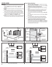
System Location
For pedestrian door or gate installations, mount the Entry System
on a rigid wall near the controlled door. Avoid mounting the unit
in a location where regular mechanical shock will occur due to a
slamming door or spring loaded pedestrian gate.
For vehicular gate installations, mount the Entry System in clear
view of the gate, but far enough from the gate so the user cannot
touch the gate from the keypad.
★ WARNING FOR ALL GATE INSTALLATIONS: TO AVOID
SERIOUS INJURY OR DEATH, MAKE SURE THAT THE
UNIT IS FAR ENOUGH FROM THE GATE SO THAT THE
USER CANNOT TOUCH THE GATE WHILE OPERATING
THE KEYPAD. HOWEVER, FOR SAFETY, THE GATE
MUST BE FULLY VISIBLE FROM THE KEYPAD.
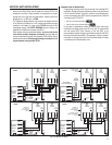
Telephone Wires
The quality of the system’s audio communications is related to the
type of telephone wire and its installation. Noise and hum can be
introduced into the telephone wires. Use only high-quality telephone
wire rated for direct underground burial. All telephone wire should
be twisted-pair.
• Minimum size of 24 AWG for up to 800 feet.
• Minimum size of 22 AWG for up to 1600 feet.
• Minimum size of 20 AWG for up to 2200 feet.
• Minimum size of 18 AWG for up to 3600 feet.
DO NOT ROUTE TELEPHONE AND AC WIRING INSIDE THE
SAME CONDUIT. Route all telephone wires inside a dedicated
conduit that is at least six inches away from any AC line wiring.
Power Supply
Use the supplied 16-volt 20-VA transformer to power the RE-2.
DO NOT POWER ANY OTHER EQUIPMENT FROM THE SAME
TRANSFORMER, use a separate power supply. Keep the system
power wires as short as practical to reduce the chance of noise and
hum pickup.
• For low voltage power wire runs up to 100 feet, use 18 AWG, THHN
600-volt insulated wire.
• For low voltage power wire runs up to 200 feet, use 16 AWG, THHN
600-volt insulated wire.
• Use 22 AWG or larger (depending on the load) for all other
connections.
ALWAYS REMOVE POWER PRIOR TO SERVICING
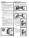
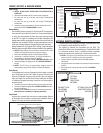
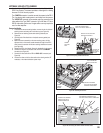
Earth Ground
To avoid damage to the unit from static discharges, connect the
RE-2’s EARTH GROUND and case ground terminals to a good
earth grounding point within 10 feet. The case ground terminal is
the #8 screw located on the lower right corner of the rear case.
Also, the RE-2’s Telephone Bypass Module must be grounded to
provide surge protection for the telephone line. Suggested wiring
size is 12 AWG for earth ground.
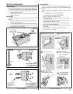
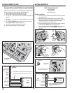
Removable Terminal Blocks
For convenience, the RE-2 is provided with removable terminal
blocks. It is important that these blocks be removed evenly in order
to avoid causing permanent damage to them.
1. Be certain power is off before removing or installing the terminal
blocks.
2. Squeeze the terminal block sides between your thumb and index
fi nger.
3. Rock the terminal block left and right while gently pulling it out.
4. When re-installing the terminal blocks, press the block in straight and
evenly.
✦ NOTE: Unscrew the terminal screws several turns before inserting
wires.