


Iris Touch 200 Range Dialer Installation Manual4
3. Alarm dialer interface
IRIS dialers carry alarm signals from the alarm panel over IP completely
transparently so when they arrive at the Monitoring Centre it is as though they
had come over a traditional PSTN connection. IRIS dialers support SIA (Levels
1 to 3), Contact ID, Scancom (Fast Format) and Robofon protocols, one of
which virtually all alarm panels will support.
Apart from the following, no reconfiguration of the alarm panel is required for
use with IRIS dialers:
1. If alarm signalling over Ethernet or GPRS is required, change the setting in
the alarm panel for the telephone number to be dialled for alarm signalling.
This number should be changed to the IP address of the Monitoring Centre,
entered as 12 digits. Each of the four IP address numbers separated by a ‘.’
should be entered as a 3 digit number, with leading ‘0’s as required, and
the ‘.’s should be excluded. For example:
IP address 10.1.146.22 is entered as 010001146022.
If the Monitoring Centre requires a backup IP address to be entered, this is
done in the same way.
2. If alarm signalling over GSM is required, add a leading digit ‘7’ to the
normal PSTN telephone number of the Monitoring Centre.
3. If the panel is required to make outgoing calls over IP for upload/download
or remote configuration, then where the telephone number for this would
normally be entered, put in the digit ‘8’ followed by the destination IP
address in 12 digit format, as above.
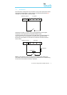
4. Installing the IRIS Touch Dialer
Use the following procedure to install the IRIS Touch Dialer.
Note: For installations using PIN alarm inputs see the PIN alarms section for
additional information and for wiring to relay outputs see the Relay outputs
section.
Do not apply power to the dialer until indicated.