


Iris Touch 200 Range Dialer Installation Manual 11
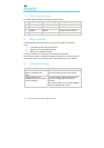
Appendix A – Settings menu
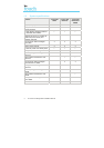
Setting Purpose
Network Interfaces Selects which network interfaces are going to be used (i.e.
Ethernet and/or Ethernet/GPRS). Stops dialer reporting trouble
on interfaces not being used.
Account Number/Name The IRIS account number/name, as allocated by the Monitoring
Centre.
Monitoring Centre IP
Address
IP address of the receiver at the Monitoring Centre.
Dialer IP Address IP address of the dialer, i.e. either automatic (DHCP) or fixed.
GPRS Settings GPRS Access Point Name (APN), user name and password.
View signal strength.
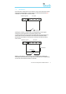
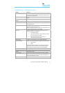
Alarm Panel Interface Selects whether or not the 2-wire cable to the dialer is
monitored for short and open circuit.
Note: For monitoring to function correctly a sense resistor must
be fitted as described earlier in this manual.
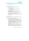
Pin Inputs Selects whether or not pin input is monitored (using sense
resistors) and selects input function:
• Send SMS message.
• Send SIA format alarm over IP (trouble and restore
event codes and zone number).
• Send Fast Format alarm over IP (alarm or
open/close) and set pin polarity.
Relay Outputs Activation of relay outputs by incoming SMS messages.
Trouble Reporting Selects how local communications problems are reported, via:
• Relay outputs.
• SMS.
Sets the text string that appears on screen to advise the user
what action to take (e.g. support centre telephone number).
Sets IP address of support centre for remote diagnostics.
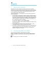
Language Selects language.
Installer Password Sets a password to the Installer menus, if required.
Contrast Sets display contrast.
Tamper restore Clears tamper alarm if tamper switches have been triggered.
Audio The dialer has a diagnostic tool with integral speaker to allow
the audio signal to and from the alarm dialer to be heard. The
audio can be switched on and off.
Default all Sets all settings back to factory defaults.