


Iris Touch 200 Range Dialer Installation Manual 5
1. Decide where to run the cables
Decide the best way to run the cables to the PCB. This can be either:
• Behind the unit (through the wall).
• Through the bottom of the back plate of the unit (via the ‘knock outs’).
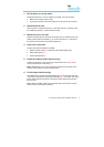
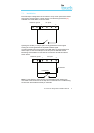
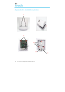
2. Disassemble the unit
Remove the two case fixing screws [1] and open the unit [2]. Remove the
two PCB fixing screws [3] and remove the PCB.
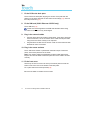
3. Mount the unit on the wall
Position the back plate on the wall, drill 3 holes, put the cables through the
opening at the base of the plate [4], or via the ‘knockouts’ [5], and secure
the plate to the wall with the 3 screws supplied [6].
4. Plug in the connectors
Connect the relevant cables to the PCB:
• Ethernet cable (cream) [7] (Ethernet / Ethernet & GPRS only)
• Dialer cable (grey) [8]
• Power cable (black) [9]
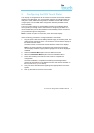
5. Install the antenna (GSM / Ethernet only)
Position the antenna in the groove in the back plate of the unit [10] and
connect the antenna to the PCB [11].
Note: Alternatively you can use an external antenna if the location of the
internal antenna does not give sufficient signal.
6. Fit the tamper switch springs
The IRIS dialer is protected against tampering (e.g. removal from the wall
or opening of the case) by two tamper switches [12] – one either side of the
PCB. These switches are held by springs that press against the wall and
the top cover.
Before fitting the PCB, make sure the springs that come with the unit are
fitted correctly to the tamper switches.