


Iris Touch 200 Range Dialer Installation Manual 3
2. Before you start…
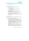
2.1. Package contents
In this package you should have the following components:
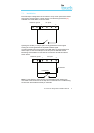
• Main dialer unit comprising:
• PCB with 3 part plastic enclosure (back, front and slider).
• 4 x assembly screws.
• 2 x tamper switch springs.
• Power cable (black) for connection to DC supply.
• Ethernet cable (cream) for connection to IP network. (Ethernet /
Ethernet & GPRS only).
• Antenna for GSM/GPRS. (GSM / Ethernet & GPRS only).
• Dialer cable (grey) for connection to dialer output of alarm panel.
• Screws and plugs (3 of each) for wall mounting.
• Sense resistor (18K ohm) for alarm dialer cable fault/tamper detection.
• Installation manual.
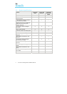
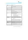
2.2. Pre-requisites
For installations using IP (Ethernet) or GPRS you must ensure you have the
following:
• The IP address for the Monitoring Centre.
• Confirmation that the Monitoring Centre is set up and ready for the
account number or name to be used for this IRIS dialer.
• The type of IP address (either automatic or fixed) for the installation
site. If the site has a fixed IP address, you should get this information
from the customer in advance, together with the Gateway Address and
the Subnet Mask for the IRIS dialer.
• An additional long Ethernet cable, in case the installation site requires
one longer than that supplied with the IRIS dialer.
• A SIM card enabled for GPRS with the PIN code clear. (Ethernet &
GPRS only.)
• The GPRS Access Point Name (APN) of the SIM card provider. Some
networks also require a User Name and Password which can also be
obtained from the SIM card provider. (Ethernet & GPRS only.)