


Iris Touch 200 Range Dialer Installation Manual 9
Reference
g
round
Pin inputs
14
4K7 Resistor
15K
Resistor
14
Reference
g
round
Pin inputs
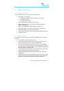
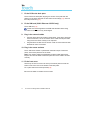
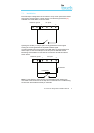
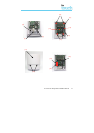
7.1. Installation
Each PIN input is designed to be connected in a loop via an open/close contact
source from an alarm panel, or other device, to a reference ground PIN [19]
available on the IRIS dialer, as shown below:
Opening the contact (i.e. loop is open circuit) generates an alarm signal.
Closing the contact generates the equivalent restore signal.
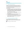
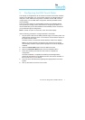
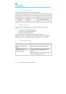
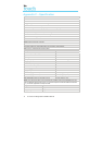
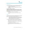
It is also possible to link the contacts to the IRIS dialer via sense resistors so
that an open or short circuit tamper on the loop can be detected and the
Monitoring Centre alerted. In this case the connections should be made as
shown below:
Note: For this feature to work correctly it is essential that the resistors are
connected at the contact end of the loop and not the dialer end. The Monitoring
Centre must also enable this facility on the dialer.