


Iris Touch 200 Range Dialer Installation Manual6
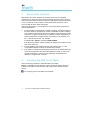
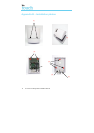
7. Fit the PCB to the back plate
Fit the PCB to the back plate, aligning the corners of the plate with the
edgings on the back plate and the two bottom screw fittings [13]. Screw in
the 2 top screws only [14].
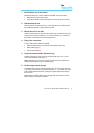
8. Fit the SIM card (GSM / Ethernet & GPRS only)
Fit the SIM card [15].
Power must not be applied to the PCB while the SIM card is being
fitted or removed or it may be damaged.
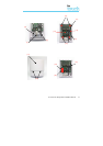
9. Plug in the external cables
• Plug the dialer cable into the alarm panel dialer. If the alarm panel has
screw connections, cut the connector off the cable and strip the cable
using the 2 inner wires. Polarity is not important.
• Plug the Ethernet cable into the local IP router or socket that has been
allocated for the IP connection.
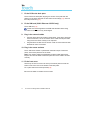
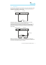
10. Plug in the sense resistors
Fit the 18K sense resistor in parallel with the dialer output of the alarm
panel, at the alarm panel end of the cable.
Note: This resistor enables the IRIS dialer to detect cable faults and/or
tampers and must be fitted at the alarm panel end of the cable to function
correctly.
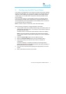
11. Fit the front cover
Slot the top of the front cover into the top of the back plate and click the
bottom of the front cover to the bottom of the back plate.
Fix in place with the 2 screws provided [16].
Pull down the slider to reveal the touch screen.