


18
MODEL 6081-P pH/ORP SECTION 5.0
OPERATION WITH REMOTE CONTROLLER
5.3 VERIFY OPERATION
Operation can be verified in three locations, at the device via the Local Display, using the 375 Field Communicator,
or at the Gateway via the 1420 Wireless Gateway’s integrated web server.
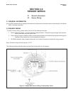
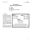
Local Display: During normal operation, the LCD will display the PV value at the wireless transmit rate up to as
fast as 1 second intervals. Refer to LCD Screen. Access the information screens by pressing the down key to dis-
play the TAG, Device ID, Network ID, Network Join Status and Device Status screens. For Device Status screens.
375 Field Communicator: To verify device operation using a HART Field Communicator, a 6081 DD is required.
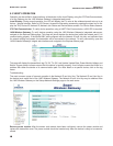
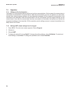
1420 Wireless Gateway: To verify device operation using the 1420 Wireless Gateway’s integrated web server,
navigate to the Explorer>Status page. This page will show whether the device has joined the network and if it is
communicating properly. If the Model 6081 was configured with the Network ID and Join Key and sufficient time
for network polling has passed, the transmitter will be connected to the network. To verify connectivity, open the
1420 Wireless Gateway’s integral web interface and navigate to the Explorer>Status page.
This page will display the transmitter’s tag, PV, SV, TV, QV, Last Update, Update Rate, Power Module Voltage, and
Status. A green status indicator means that the device is working properly. A red indicator means that there is a
problem with either the device or its communication path. For more detail on a specific device, click on the tag
name.
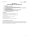
Troubleshooting
The most common cause of incorrect operation is the Network ID and Join Key. The Network ID and Join Key in
the device must match that of the 1420 Wireless Gateway. The Network ID and Join Key may be obtained from
the 1420 Wireless Gateway on the Setup>Network>Settings page on the web server.
18
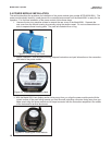
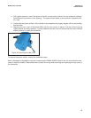
Remove power module: After the sensor and network have been configured, remove the power module and
replace the transmitter cover. The power module should be inserted only when the device is ready to be commis-
sioned.