


6
2.3 PRE-INSTALLATION SETUP
2.3.1 Temperature Element
The Model 6081-P pH/ORP transmitter is compatible with sensors having Pt 100 and Pt 1000. Sensors from other
manufacturers may have a Pt 1000 RTD. For Rosemount Analytical sensors, the type of temperature element in
the sensor is printed on the tag attached to the sensor cable. For the majority of sensors manufactured by
Rosemount Analytical, the RTD IN lead is red and the RTD RTN lead is white. The Model 328A sensor has no
RTD. The Model 320HP system has a readily identifiable separate temperature element. Resistance at room
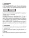
temperature for common RTDs is given in the table.
If the resistance is... the temperature element is a
about 110 ohms Pt 100 RTD
about 1100 ohms Pt 1000 RTD
2.3.2 Reference Electrode Impedance
The standard silver-silver chloride reference electrode used in most industrial and laboratory pH electrodes is low
impedance. EVERY pH and ORP sensor manufactured by Rosemount Analytical has a low impedance reference.
Certain specialized applications require a high impedance reference electrode. The transmitter must be
re-programmed to recognize the high impedance reference.
2.3.3 Preamplifier Location
pH sensors produce a high impedance voltage signal that must be preamplified before use. The signal can be
preamplified before it reaches the transmitter or it can be preamplified in the transmitter. To work properly, the
transmitter must know where preamplification occurs. Although ORP sensors produce a low impedance signal, the
voltage from an ORP sensor is amplified the same way as a pH signal.
If the sensor is wired to the transmitter through a junction box, the preamplifier is ALWAYS in either the junction
box or the sensor. Junction boxes can be attached to the sensor or installed some distance away. If the junction
box is not attached to the sensor, it is called a remote junction box. In most junction boxes used with the Model
6081-P pH/ORP, a flat, black plastic box attached to the same circuit board as the terminal strips houses the pre-
amplifier. The preamplifier housing in the 381+ sensor is crescent shaped.
If the sensor is wired directly to the transmitter, the preamplifier can be in the sensor or in the transmitter. If the
sensor cable has a GREEN wire, the preamplifier is in the sensor. If there is no green wire, the sensor cable will
contain a coaxial cable. A coaxial cable is an insulated wire surrounded by a braided metal shield. Depending on
the sensor model, the coaxial cable terminates in either a BNC connector or in a separate ORANGE wire and
CLEAR shield.
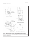
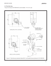
2.4 Mechanical Installation
When choosing an installation location and position, take into account the need for access to the transmitter. For
best performance, the antenna should be vertical with some space between objects in a parallel metal plane such
as a pipe or metal framework, as the pipes or framework may adversely affect the performance of the antenna.
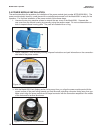
2.5 Ground the Transmitter
The electronics enclosure should be grounded in accordance with local and national installation codes. This can
be accomplished via the process connection, via the internal case grounding terminal, or via the external ground-
ing terminal.
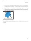
mV and RTD Inputs
Each process installation has different requirements for grounding. Use the grounding options recommended by
the facility for the specific sensor type, or begin with grounding Option 1 (the most common).
MODEL 6081-P pH/ORP SECTION 2.0
INSTALLATION