88
Filter Nodes
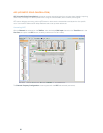
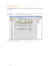
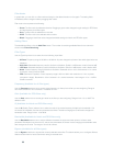
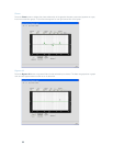
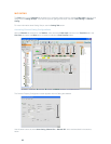
In graph view, you can click on a filter node and drag it to the desired location on the graph. The setting fields
immediately reflect changes made by dragging filter nodes.
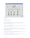
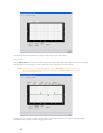
Filter node colors represent the following:
Green• : The filter node is selected and active. Dragging a green node changes the gain setting for PEQ filters
and the frequency for all filter types.
Grey• : The filter node is selected but not active.
White• : The filter node is not selected and not active.
Black• : Dragging a black filter node changes bandwidth settings for Notch and PEQ filter types.
Adding Filters
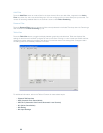
To add additional filters, click the Add Filter button. The number of remaining available filters for the channel is
shown under Filters Remaining.
Filter Types
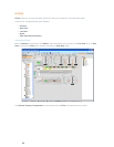
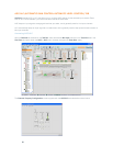
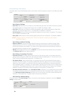
Use the Type drop-down list to select from the following input filters:
All Pass• . Frequency range is 20.00Hz to 20.00kHz. All pass changes the phase of the audio signal at the set
frequency.
High Pass.• Selectable frequency cutoff is 20.00Hz to 20.00kHz. Rolloff is 12dB/octave. Level is fixed at 0dB.
Low Pass.• Selectable frequency cutoff is 20.00Hz to 20.00kHz. Rolloff is 12dB/octave. Level is fixed at 0dB.
Notch• . Center frequency range is 20.00Hz to 20.00kHz. Bandwidth is from .05 to 5.00 octaves in .01 octave
increments. Level is fixed at -80dB.
PEQ • (Parametric Equalizer). Center frequency range is 20Hz to 20kHz with resolution to 1Hz or 4 places
(whichever is larger). Bandwidth is .05 to 5 octaves in .01 octave increments. Level range is -15 to +15dB in
0.5dB increments.
Frequency (Available for all filter types)
Use the Frequency selector box to set the center frequency (in Hertz) for the filter you are configuring. Range is
from 20Hz to 20kHz in 1Hz increments. The default is 1kHz.
Gain (Available for PEQ filters only)
Use the Gain selector box to set the gain value for the filter you are configuring. Range is from -15 to 15dB. The
default is 0dB.
Q (Available for Notch and PEQ filters only)
Use the Q (Quality Factor) selector box to select the ratio of the center frequency divided by the bandwidth. Q is
the inverse of bandwidth, and the two parameters are linked. Therefore changing the Q value also changes the
bandwidth value. Range is from .18 to 28.85.
Bandwidth (Available for Notch and PEQ filters only)
Use the Bandwidth selector box to set the difference between the upper and lower points of a filter’s audio
passband. Bandwidth is the inverse of Q, and the two parameters are linked. Hence changing the bandwidth value
also changes the Q value. The range is .05 to 5.00 octaves.
Bypass (Available for all filter types)
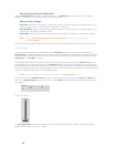
Use the Bypass checkbox to bypass the currently selected active filter. This feature allows you to configure different
filters and save them for future use without having to recreate them.


