E-2
Cisco Unified IP Phone 7960G/7940G Administration Guide for Cisco Unified Communications Manager 7.0 (SCCP)
OL-15498-01
Appendix E Technical Specifications
Cable Specifications
Cable Specifications
• RJ-9 jack (4-conductor) for handset and headset connection.
• RJ-11 jack for console access (labeled AUX or RS232).
• RJ-45 jack for the LAN 10/100BaseT connection (labeled LAN).
• RJ-45 jack for a second 10/100BaseT compliant connection (labeled PC).
• 48-volt power connector. The diameter of the center pin in the phone power jack (Switchcraft 712A)
is 0.1 in. (2.5 mm). The center pin is positive (+) voltage. The miniature power plug required to mate
with the power jack on the phone is a Switchcraft 760 or equivalent.
Network and Access Port Pinouts
Although both the network and access ports are used for network connectivity, they serve different
purposes and have different port pinouts.
Network Port Connector
Table E-2 describes the network port connector pinouts.
Ta b l e E-2 Network Port Connector Pinouts
Pin Number Function
1 TD+
2 TD-
3 RD+
4 +48 Volts return
1. When used to receive power from an inline
power card in the Cisco Catalyst switch.
1
5 +48 Volts return
1
6 RD-
7 +48 Volts source
1
8 +48 Volts source
1
Access Port Connector
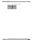
Table E-3 describes the access port connector pinouts.
Ta b l e E-3 Access Port Connector Pinouts
Pin Number Function
1 RD+
2 RD-
3 TD+
4 Not Used
5 Not Used


