


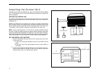

Installing the Control Unit
Installation procedures are basically the same for both Model 206 and Model
410. The instructions point out only those differences between the models that
affect installation.
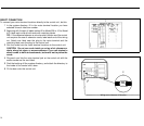
POSITION THE CONTROL UNIT
If you plan to wall mount your control unit, follow the instructions in the booklet
titled CIB 3029 (for Model 206) or CIB 3030 (for Model 410) in your Control Unit
Installation Kit.
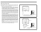
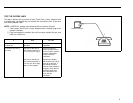
Whether you wall mount your control unit or place it on a table or shelf, make
sure it’s within 5 feet of an ac outlet that is not switch-controlled, within 5 feet
of the network interface, and within 6 inches of the jack field, if you have one.
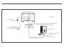
The drawing, right, provides a diagram for positioning the control unit.
5 feet, maximum
6 inches, maximum
5 feet, maximum
NOTE:
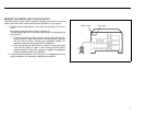
The ac outlet should be a 117-volt, 60-Hz, 3-prong, third-wire ground-
ed outlet. Proper grounding protects the system against damage from power
surges caused by static discharge and lightning. You should have an electri-
cian check the outlet’s third wire to make sure the outlet is properly grounded.
Power consumption for both models is 40 watts during normal operation.
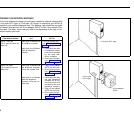
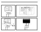
SET THE CONTROL UNIT SWITCHES
1
2
●
●
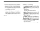
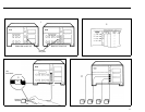
Find the Tone/Pulse switch near the top of the center panel on the front
of the control unit.
If you have rotary (pulse) telephone service, set the switch to Pulse
(right).
If you have Touch-Tone signal telephone service, set the switch to
Tone (left).
Find the row of switches labeled Ringing on the left panel of the con-
trol unit. Set all of them to Yes (up) for now. You may want to reset these
switches later when you customize your system.
1
Tone/Pulse switch
2
Ringing switches
6