


Voice Terminal Wiring
The intercom number for each voice terminal in your
MERLIN
system is the
same as the number of the voice terminal jack on the control unit to which that
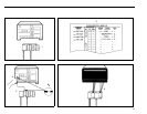
voice terminal is connected. On a Model 206 control unit, the voice terminal
jacks are numbered 0 through 5. On a Model 410 control unit, the voice terminal
jacks are numbered 10 through 19. If you want a particular intercom number
at a specific location within your business, make a note of the assignment now,
before you begin connecting the voice terminal locations to the system.
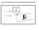
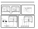
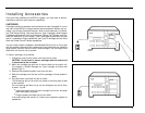
You can connect your voice terminal locations to the control unit either of two
ways: (1) directly, with modular jumper cords and, if needed, modular exten-
sion cords; or (2) indirectly, through the building wiring to a jack field at the con-
trol unit location.
Whichever procedure you use, you need the following items from the installa-
tion kit to complete the connections:
System directory
You’ve already recorded the telephone numbers for your outside lines on it.
Modular jumper cords
You should have one 2½-foot cord for each intercom in your system. If you
have a professionally installed jack field, these cords may be hanging from
the jacks in the jack field. If they are, remove them now.
Blue-on-white jumper cord labels
You should have a matched pair for each cord. The label numbers are 0
through 5 for Model 206 and 10 through 19 for Model 410.
The next two sections give instructions for a jack field connection and a direct
connection. Go to the section that applies to your system and do what it says.
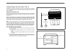
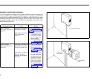
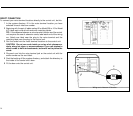
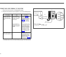
JACK FIELD CONNECTION
To connect the control unit to the jack field, do this:
1
2
3
4
5
6
7
8
Open the right door of each jack panel box in the jack field.
TIP: The labeling inside the right door should indicate the wiring run
number and endpoint for each jack in the box. Use this labeling as a
guide when you fill in your system directory and connect the jacks in
the jack field to the voice terminal jacks on the control unit.
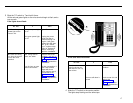
In the system directory, fill in the voice terminal location (the wiring run
endpoint) for each intercom number.
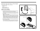
Beginning with the pair of labels marked 0 for a Model 206 or 10 for a
Model, 410, label both ends of each jumper cord with matching jumper
cord labels.
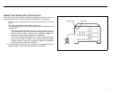
Plug one end of the cord labeled with the first intercom number (0 or
10) into the voice terminal jack on the control unit with the same number.
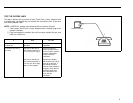
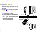
Following the system directory and the jack field labeling, plug the other
end of the cord into the jack in the jack field for the voice terminal loca-
tion to which you have assigned that intercom number.
Repeat the procedure for each modular jumper cord, and close the jack
panel box doors when you’re finished.
Peel the backing off the system directory, and attach the directory to
the inside of the control unit’s door
Fit the door onto the front of the control unit.
●
●
●
12