


Model 45 User Guide Issue Preliminary 2, March 2009
Studio Technologies, Inc. Page 9
audio quality, advanced users might need
to disable it. This would allow full control
over the Model 45’s two hybrid circuits,
enabling them to be used in a completely
independent manner.
Simple Installation
The Model 45 uses standard 3-pin XLR-
type connectors, allowing convenient 2-wire
party-line and 4-wire interconnection in
broadcast and general audio environments.
For flexibility, access to the 2-wire party-line
intercom interface can be made using
either a male or female XLR connector.
In many applications the Model 45 will be
powered by an external source of 24 volts
DC. A compact, lightweight 24 volt DC out-
put power source is supplied with each unit.
The power supply’s universal mains input
capability (100-230 volts, 50/60 Hz) allows
operation virtually anywhere in the world.
The Model 45 can also be powered by the
connected 2-wire party-line intercom circuit.
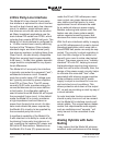
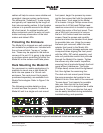
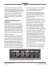
The four LED meters (previously mentioned)
make it simple to confirm operation of the
connected 4-wire inputs, 4-wire outputs,
and 2-wire party-line circuit. Additional LED
status indicators are also provided, offering
a clear view of the 2-wire DC power source,
auto null functions, and input operating
power.
The Model 45 is housed in a rugged,
lightweight aluminum enclosure that is
designed to be “road tough.” The half-rack
unit is ready for portable or stand-alone
“thrown-down” applications. Optional “1U”
front panels allow one or two Model 45
units to be mounted in one space of a
standard 19-inch rack enclosure.
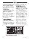
Design Philosophy
While the “bits and pieces” that make up
the Model 45 have been described in con-
ventional terms, the real strength of the unit
rests in the way it integrates and performs
in the “real world.” Studio Technologies
learned from conversations with indus-
try experts that installing and configuring
2-wire-to-4-wire interface equipment has
traditionally been a time-consuming, ag-
gravating process, requiring the efforts of an
expert to achieve reasonable results. And
even under those constraints the resulting
audio performance was often mediocre.
This “history lesson” made it clear that any
new design had to start with a unique set
of requirements. This led to an overriding
design goal: create a “new breed of cat,”
fundamentally changing how broadcast
2-wire-to-4-wire interface equipment fits into
actual applications.
An important first step was to eliminate
the requirement that a senior technician,
along with a screwdriver, be present dur-
ing every installation. (It was universally
acknowledged that their time can be better
spent elsewhere!) The need to adjust trim
potentiometers, fabricate special cabling
and connector straps, use nulling ear-
pieces, etc. had to be eliminated. For ex
-
ample, in virtually all instances, input and
output levels fall within just a few dB of their
nominal values and, as such, could be sup-
ported with one industry-standard nominal
audio level. In addition, it was acknowl-
edged that in this application analog audio
circuitry was capable of providing excellent
audio performance, but that the required
manual nulling process was operation-
ally taxing. By adding digital control to the
analog circuitry, automatic nulling could be
performed—the best of both worlds!