


Issue Preliminary 2, March 2009 Model 45 User Guide
Page 24 Studio Technologies, Inc.
readily apparent. The front-panel LEDs will
continue to display the DC power status of
pins 2 and 3. But whether or not either or
both LEDs are lit, the Model 45 will never
apply 200 ohm terminations to pins 2 or
3. For the hybrid circuits to remain stable
termination impedances must be provided
by the connected circuits. If these are not
present one might find the hybrid circuits
generating very unpleasant audible noise.
This condition, caused by the 2-wire out-
put circuitry being in an “unloaded” state,
will not damage the Model 45’s circuitry.
However, without the auto terminate func-
tion a disconnected cable or other real-
world wiring problem could present users
with a rude surprise!
In conclusion, it’s important that technical
personnel working with the Model 45 be
informed when the auto termination func-
tion has been disabled. They will then be
aware of the potential noise issues and be
ready to make corrections should a prob-
lem arise.
4-Wire Mute During Auto Null
Normally, the 4-wire outputs are muted
whenever the auto null process is taking
place. This ensures that the test tones
generated as part of the nulling process
will not be heard by users of the signals
associated with the 4-wire outputs. For
special applications configuration DIP
switch 5 allows the automatic muting
mode to be disabled. This mode is pro-
vided primarily for use by factory person-
nel or during demonstration use. During
normal operation switch 5 should remain
in its off (down) position. When switch 5 is
in its on (up) position 4-wire muting dur-
ing auto null will not take place. While not
appropriate during actual Model 45 use, it
is interesting to “hear” the nulling process
take place. But unless there’s a really good
reason, configuration DIP switch 5 should
always remain in its off (down) position.
Technical Notes
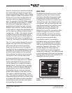
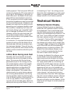
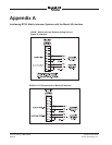
Software Version Display
A special Model 45 power-up sequence
allows the unit’s software version number
to be displayed. This is useful when work-
ing with factory personnel on application
support and troubleshooting situations. The
five “from” 4-wire LEDs are used to display
the major release number with a range of
1 through 5. The five LEDs associated with
“to” 4-wire channel 1 are used to display
the release sub-number which ranges from
1 through 5. Refer to Figure 8 for a detailed
view of the LEDs and the corresponding
software version numbering scheme. The
Model 45’s initial software release is ver-
sion 1.1 which is represented by the bot-
tom LED of each column being lit.
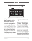
To display the Model 45’s software version
is very simple. From the powered-down
state, press and hold the auto null button.
While continuing to press the auto null but-
ton, apply power either by connecting an
external 24 volt DC power source or a pow-
ered intercom circuit. The normal power-up
sequence will not occur but instead one
LED in the status column will be lit and one
LED in the column associated with “from”
4-wire channel 1 will also be lit. As previ-
ously described, these two LEDs represent
the unit’s current software version. After the
software version number has been “read”
the auto null button can be released. At this
time the unit will begin its normal power-up
sequence.