


Model 45 User Guide Issue Preliminary 2, March 2009
Studio Technologies, Inc. Page 25
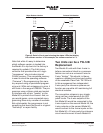
Note that while it’s easy to determine
which software version is loaded into
the Model 45 a trip back to the factory is
required to update it. The 8-bit micro-
controller that provides the unit’s logic
“horsepower” also includes internal
FLASH memory. This nonvolatile memory
is used to store the operating software
(“firmware”). Re-programming this mem-
ory requires using a specialized program-
ming unit. While not outrageous in price, it
still costs in the range of US$500. The pro-
grammer uses a ribbon cable and socket
to interface with a 6-pin “header” on the
Model 45’s printed circuit board. And, as
you would guess, once connected repro-
gramming takes only a matter of seconds.
But unfortunately the programmer is not
something that would be found in a typical
“field shop” or repair facility.
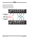
Two Units can be a TW-12B
Replacement
Two Model 45 units with their 4-wire in-
terface connectors linked in a crossover
fashion can act as a universal 2-wire-to-
2-wire “bridge.” This should, in theory,
create an updated and improved version
of the venerable Clear-Com TW-12B unit.
In this arrangement two independent
2-wire party-line intercom systems can
function as one while still maintaining full
electrical isolation.
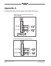
The connection scheme is very simple,
using just four male-female 3-pin XLR
patch cords. The 4-wire outputs of the
first Model 45 would be connected to the
4-wire inputs on the second Model 45; the
4-wire outputs on the second Model 45
would connect to the 4-wire inputs on the
first Model 45. A 2-wire party-line intercom
circuit would connect to each Model 45
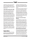
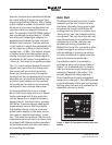
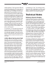
Figure 8. Detail of front panel showing the status LEDs that display
the software version. In this example, the software version is 1.3.
Major Release Number Release Sub-Number
O 4 .4 O
O 3 .3
O 2 .2 O
1 .1 O