


Model 45 User Guide Issue Preliminary 2, March 2009
Studio Technologies, Inc. Page 11
cables will help to ensure more reliable and
consistent intercom system performance.
The differential (“balanced”) 4-wire circuits
are typically not impacted by the length of
their interconnecting cables. A final location
criterion is to provide access to the Model
45’s front panel. An optimal location will
allow convenient use of the auto null push-
button and easy observation of the level
meters and status LEDs.
Protecting the Enclosure
The Model 45 is shipped as a self-contained
unit suitable for portable use. Included with
the unit are self-stick “bump on” protec-
tors. These may be applied to the bottom
corners of the unit if it is going to be placed
on surfaces where scratching of either the
Model 45 or the surface could take place.
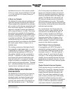
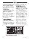
Rack Mounting the Model 45
For permanent or mobile applications it’s
possible to mount one or two Model 45
units into one space of a 19-inch rack
enclosure. Two rack-mount front panels,
purchased separately, are available from
Studio Technologies. Refer to Figure 3 for
details.
The following provides details on how
to install and use the panels. To attach a
Model 45 unit to a single-unit rack-mount
front panel, begin the process by remov-
ing the five screws that hold the standard
“throw-down” front panel to the Model
45’s chassis. Using a Phillips screw driver,
remove the 4-40 flat-head Phillips-head
machine screw which is located in approx-
imately the center of the front panel. Then
use a 5/64-inch hex wrench to remove
the four 4-40 button-head hex machine
screws. Save the screws and carefully
protect and store the standard front panel
for possible later use. Using the screws
that were just removed, attach the rack-
adapter front panel to the Model 45’s
chassis. To prevent damage extreme care
is required when aligning the front panel
with the LEDs, DIP switch assembly, and
auto null pushbutton switch that protrude
through the Model 45’s chassis. Tighten
the screws only after careful inspection,
ensuring that all protrude through the front
panel without interference. The center
(Phillips-head) screw should be tightened
first, then tighten the remaining four.
The dual-unit rack-mount panel follows
the same procedure but applies to two
Model 45 units. Store both of the removed
“thrown-down” front panels for possible
later use. Note that on the front-panel
graphics one unit is designated as A while
the other B. This is provided so that each
can be easily identified during installation,
troubleshooting, and operation.
Figure 3. Model 45 shown in optional single-unit and dual-unit 19-inch rack-mount panels