


Issue Preliminary 2, March 2009 Model 45 User Guide
Page 12 Studio Technologies, Inc.
Once the desired one or two Model 45
units have been installed in a rack-mount
front panel, the assembly can be mounted
into the designated equipment rack. One
space (“1U” or 1.75 vertical inches) in
a standard 19-inch equipment rack is
required. Secure the unit into the equip-
ment rack using two mounting screws
per side.
4-Wire Audio Inputs and
Outputs
Two audio line input and two audio line
output signals are associated with the
4-wire interface section of the Model 45.
Connections are made using standard
3-pin male and female XLR connectors.
Refer to Appendices A, B, and C for de-
tails on interconnecting with RTS, Riedel,
and Clear-Com matrix intercom systems.
4-Wire Line Inputs
As previously mentioned, the Model 45’s
4-wire interface allows two analog line-
level audio sources to be connected. The
source for these signals will typically be
ports on a matrix intercom system. It’s
also possible that the signals will come
from other devices, such as a fiber optic
or copper-based audio transmission sys-
tem. The 4-wire input circuitry is balanced,
capacitor coupled, transformer isolated,
and has an impedance of 13 k ohms. The
line inputs are optimized for signals that
have a nominal level of +4 dBu.
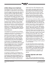
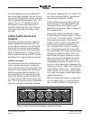
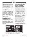
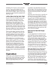
Audio sources are connected to the line
inputs by way of 3-pin female XLR-type
connectors which are located on the
Model 45’s back panel. Refer to Figure 4
for a detailed view.
Prepare the mating connectors (males)
so that XLR pin 2 is signal high (+ or hot),
pin 3 is low (– or cold), and pin 1 is shield.
If connecting a source in this manner
results in hum or noise it’s possible that
removing the shield connection from
pin 1 can eliminate the issue; “floating”
pin 1 will remove a ground current path
from the Model 45’s chassis ground point
through the shield of a cable. (Pin 1 on
each of the two input connectors is inter-
nally connected to the Model 45’s earth/
chassis ground point.) Also, if a hum or
noise issue does arise be certain to con-
firm that, unless absolutely necessary, the
mating connector’s “shell” isn’t connected
to the cables’ shield or pin 1. Termination
of this “fourth” pin of a 3-pin XLR connec-
tor is often the cause of seemingly inexpli-
cable noise issues.
With an unbalanced source connect XLR
pin 2 to signal high (+ or hot) and both
pins 1 and 3 to shield. If connecting an
Figure 4. Detail of back panel showing line inputs and outputs